
Adjustable straining beam construction formwork based on pile foundations

An adjustable, pile-based technology, applied in the direction of infrastructure engineering, construction, etc., can solve the problems of affecting subsequent structural construction, costing materials and time, and short effective operating time, so as to improve operating efficiency, improve the operating environment, and increase the window period Effect

Active Publication Date: 2017-09-05
CHINA HARBOUR ENGINEERING
View PDF5 Cites 0 Cited by
  • Summary
  • Abstract
  • Description
  • Claims
  • Application Information

AI Technical Summary

Problems solved by technology

[0002] During the construction of a cross-river or sea-crossing bridge, the construction of the substructure of the bridge is often affected by the water level of the river or the tide level of the sea, especially the design bottom elevation of the tie beam, which is generally near the low water level or the lowest tide level, and the effective operation time is very short. , which seriously affects the construction of the subsequent structure, and the usual tie beam construction is to use the engineering piles of the platform during the pile foundation construction as the supporting force-bearing structure, which is time-consuming and time-consuming, and the effective operation time is short

Method used


Image

  • Adjustable straining beam construction formwork based on pile foundations
  • Adjustable straining beam construction formwork based on pile foundations
  • Adjustable straining beam construction formwork based on pile foundations

Examples


Embodiment Construction

[0027] The present invention will be further described in detail below in conjunction with the accompanying drawings, so that those skilled in the art can implement it with reference to the description.

[0028] It should be noted that, in the description of the present invention, the terms "horizontal", "vertical", "upper", "lower", "front", "rear", "left", "right", "vertical", The orientation or positional relationship indicated by "horizontal", "top", "bottom", "inner", "outer", etc. is based on the orientation or positional relationship shown in the drawings, and is only for the convenience of describing the present invention and simplifying the description, and It is not to indicate or imply that the device or element referred to must have a particular orientation, be constructed in a particular orientation, or operate in a particular orientation, and thus should not be construed as limiting the invention.

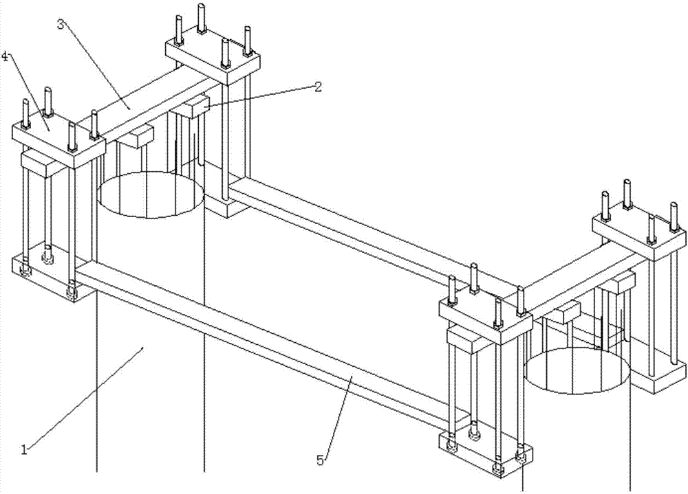
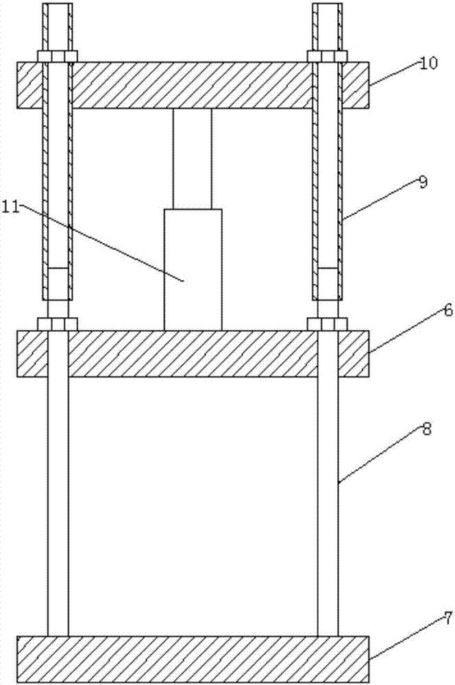
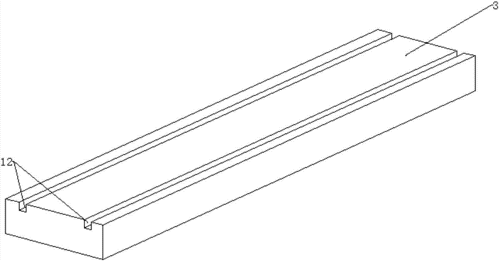
[0029] Such as figure 1 As shown, the present invention provide...


PUM


Abstract

The invention discloses an adjustable straining beam construction formwork based on pile foundations. The adjustable straining beam construction formwork based on the pile foundations comprises two groups of supporting frames, two carrying pole beams and two formwork main beams, wherein the two groups of supporting beams are fixed to steel reinforcement cages of a pair of bridge pile foundations correspondingly and are located at the same height, the two carrying pile beams are erected on the two groups of supporting frames in the direction of the bridge correspondingly and are mutually parallel, the two ends of each carrying pole beam both extend out of the ranges of the pile foundations, a bracket is hung at each end of each carrying pole beam, the upper end of each bracket is movably connected with the corresponding carrying pole beam and can move up and down, the lower end of each bracket is provided with a platform capable of bearing objects, and the two formwork main beams are horizontally erected between the brackets, on the same side, of the two carrying pole beams correspondingly, so that a framework base plate can be erected. According to the adjustable straining beam construction formwork based on the pile foundations, through the adjustable brackets, the operation environment is improved, underwater operation is changed into overwater operation, the operation efficiency of mounting and dismounting the straining beam formwork under different water level conditions is improved, the window phase of construction is prolonged, and the operation time of the straining beam at different design water levels can be ensured.

Description

technical field [0001] The invention relates to the field of bridge construction. More specifically, the present invention relates to an adjustable formwork for tie beam construction based on pile foundations. Background technique [0002] During the construction of a cross-river or sea-crossing bridge, the construction of the substructure of the bridge is often affected by the water level of the river or the tide level of the sea, especially the design bottom elevation of the tie beam, which is generally near the low water level or the lowest tide level, and the effective operation time is very short. , which seriously affects the construction of subsequent structures, and the usual tie beam construction is to use the engineering piles on which the platform is built during pile foundation construction as the supporting force-bearing structure, which is time-consuming and time-consuming, and the effective operation time is short. Contents of the invention [0003] An obje...

Claims


Application Information

Patent Timeline
Patent Type & Authority Applications(China)
IPC IPC(8): E02D27/12E02D27/52
CPCE02D27/12E02D27/52
Inventor 何俊彪
Owner CHINA HARBOUR ENGINEERING
Learn More