
An Arbitrary Delay Method for Radio Frequency Signals Based on Microwave Photon Cyclic Frequency Shift

A technology of radio frequency signal and cyclic frequency shift, applied in the field of optical communication, to prevent excessive signal power, reduce implementation cost, and simple structure

Active Publication Date: 2019-08-20
XIDIAN UNIV
View PDF3 Cites 0 Cited by
  • Summary
  • Abstract
  • Description
  • Claims
  • Application Information

AI Technical Summary

Problems solved by technology

Add an optical filter to the optical fiber ring to prevent the signal from infinitely looping and causing excessive signal power in the ring

Method used


Image

  • An Arbitrary Delay Method for Radio Frequency Signals Based on Microwave Photon Cyclic Frequency Shift
  • An Arbitrary Delay Method for Radio Frequency Signals Based on Microwave Photon Cyclic Frequency Shift
  • An Arbitrary Delay Method for Radio Frequency Signals Based on Microwave Photon Cyclic Frequency Shift

Examples


Embodiment Construction

[0035] Below in conjunction with accompanying drawing the embodiment of the present invention is described in detail: present embodiment is carried out under the premise of technical solution of the present invention, has provided detailed implementation mode and concrete operation process, but protection scope of the present invention is not limited to subordinates Example of:

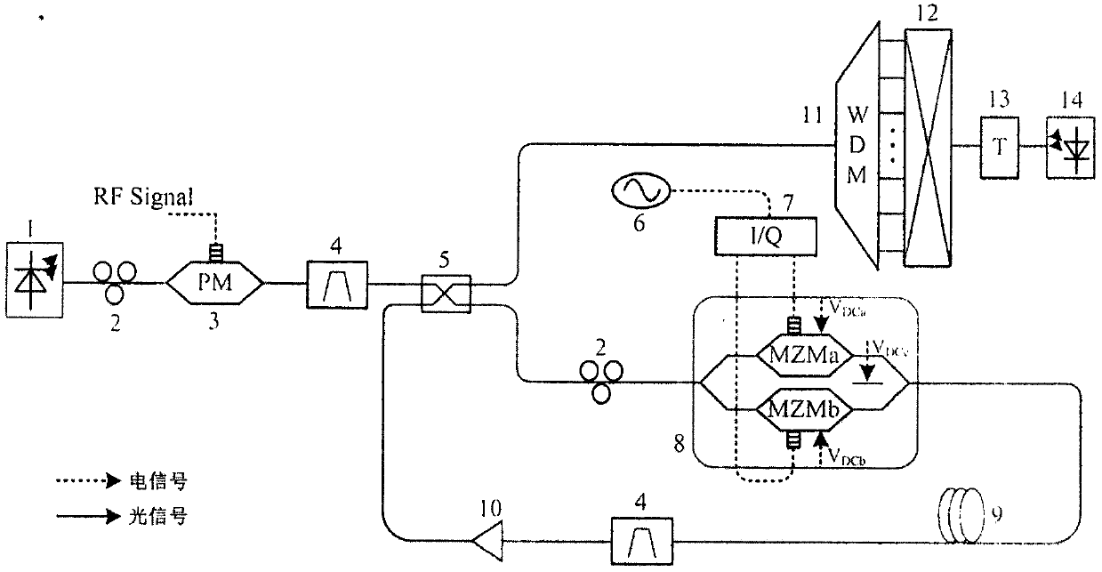
[0036] figure 1 It is a schematic diagram of an arbitrary delay device for radio frequency signals based on microwave photon cyclic frequency shift. The phase modulator is used to modulate the radio frequency signal to be stored, and the phase modulated signal passes through an optical bandpass filter to filter out a sideband of the modulated signal to obtain a single sideband modulated signal. The obtained modulated signal enters the optical fiber ring after passing through the optical coupler, and is combined with the dual parallel Mach-Zehnder modulator for cyclic frequency shift and time delay. ...


PUM


Abstract

The invention discloses a radio frequency signal random delay device and a radio frequency signal random delay method based on a microwave photon cycling frequency shift, and relates to the field of optical communication techniques, microwave techniques and electronic countermeasure techniques, mainly used for storing a radio frequency signal in an electronic countermeasure radar jamming system. The method is as shown in figures. The device comprises a light source 1, a polarization controller 2, a phase modulator 3, an optical band pass filter 4, a 2*2 optical coupler 5, a radio frequency source 6, a 90-degree radio frequency orthocoupler 7, a double parallel mach-zehnder modulator 8, a standard single mode fiber 9, an erbium-doped optical fiber amplifier 10, a wavelength division multiplexer 11, a photoswitch matrix 12, an adjustable delay module 13 and a photoelectric detector 14. The phase modulator is used for receiving the radio frequency signal. An optical loop is used for being in combination with the double parallel mach-zehnder modulator to perform frequency shift delay on the signal. And delay storage of the radio frequency signal at any time is finally achieved by the wavelength division multiplexer and the switch matrix, in combination with the adjustable delay module.

Description

technical field [0001] The invention relates to the technical fields of optical communication, microwave and electronic countermeasures, and mainly relates to the use of photonics technology to realize the reception of radio frequency signals and the storage of arbitrary delays. Background technique [0002] In modern warfare, the opposing sides will use specific electronic countermeasures to interfere with the enemy's electronic equipment. In modern radar systems, since the receivers match the waveform of the transmitted radar signal, the anti-jamming ability of the radar is strong, and the traditional jamming methods can no longer meet the needs. Therefore, for the radar jamming system, it is necessary to make a quick response to achieve the jamming effect on the enemy's radar. Therefore, not only the jamming signal sent by it is required to be highly matched with the enemy's radar signal, but also it is required to respond quickly. The radar jamming technology based on r...

Claims


Application Information

Patent Timeline
Patent Type & Authority Patents(China)
IPC IPC(8): H04B10/54H04B10/548H04B10/70H04J14/02
Inventor 修中国文爱军涂昭阳
Owner XIDIAN UNIV
Learn More