Electric control variable-curved-surface fluorescent membrane die-pressing method and apparatus
A fluorescent film and variable curved surface technology, which is applied in the direction of circuits, electrical components, semiconductor devices, etc., can solve the problems of rapidly changing the shape of the diaphragm surface, achieve the effects of improving production quality and yield, improving surface accuracy, and reducing production costs
- Summary
- Abstract
- Description
- Claims
- Application Information
AI Technical Summary
Problems solved by technology
Method used
Image
Examples
Embodiment 1
[0053] The electronically controlled variable curved surface molding fluorescent diaphragm includes the following steps:
[0054] (1) Yellow powder YG-04 is used for phosphor, HM-6101 silica gel is used for optical colloid; 10g of YG-04 phosphor, 10g of HM6101 silica gel A glue, 10g of HM6101 silica gel B glue are taken with a mass balance, YG-04 phosphor, Stir HM6101 silica gel A glue and HM6101 silica gel B glue evenly, then vacuum defoam the stirred fluorescent glue to prepare fluorescent glue;
[0055] (2) The heating device preheats the upper die base 2 and the upper die 3, the preheating temperature is 70°C, and the preheating time is 30 minutes;
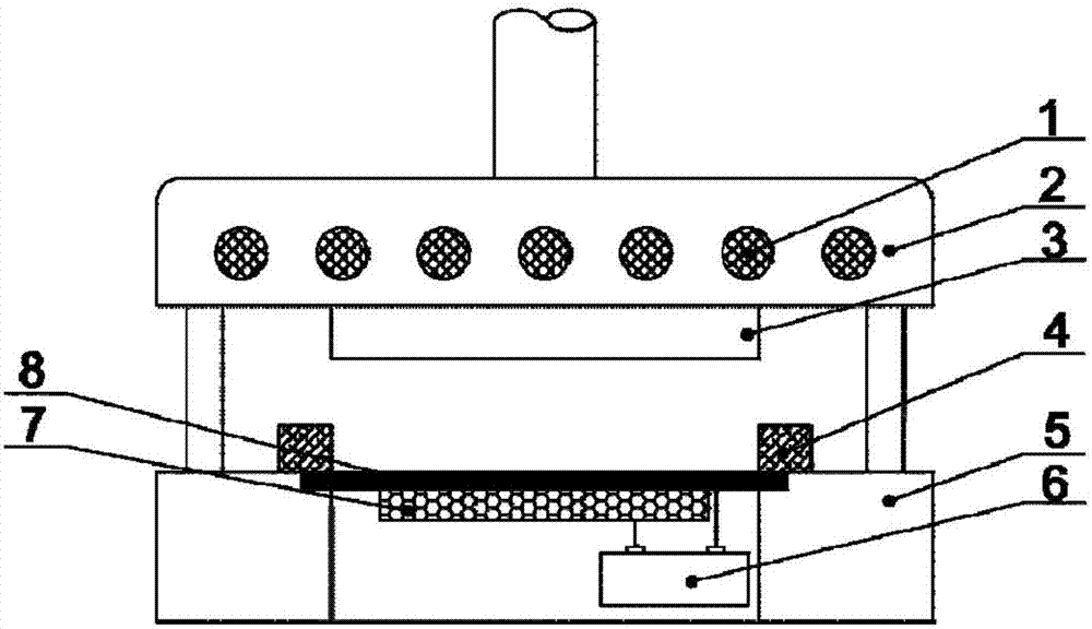
[0056] (3) Set the voltage of the adjustable voltage DC power supply 6 to 100V, and the direction is positive; if Figure 2a shown;
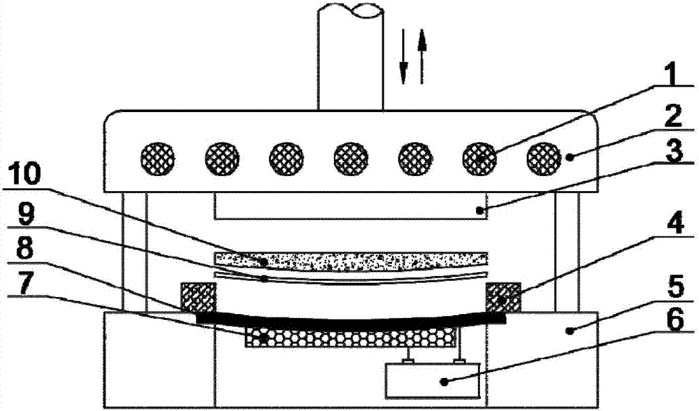
[0057] (4) Under the action of the forward voltage input by the adjustable voltage DC power supply 6, the piezoelectric material 7 is deformed, thereby driving the elastic deformation sheet 8 ...
Embodiment 2
[0065] Embodiment 2 is the same as Embodiment 1, except that steps (2), (4), (7), and (8) are as follows:
[0066] (2) The heating device preheats the upper die base 2 and the upper die 3, the preheating temperature is 90°C, and the preheating time is 20 minutes;
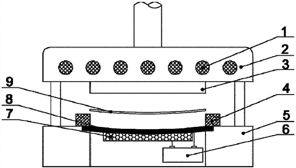
[0067] (4) Under the action of the reverse voltage input by the adjustable voltage DC power supply 6, the piezoelectric material 7 is deformed, thereby driving the elastically deformed sheet 8 to deform on a specific curved surface, forming a molded curved surface of the fluorescent film with an upwardly concave curved surface shape, Such as Figure 3b shown;
[0068] (7) The die base 2 drives the upper die 3 to move downward, and molds the uncured fluorescent glue. The upper die 3 closes with the elastic deformation sheet 8 and the dam 4. The heating device 1 will press the upper die 3 and the elastic deformation sheet Heat the fluorescent glue in the closed space formed by 8 and the dam 4 to 120°C, keep the temp...
Embodiment 3
[0071] Embodiment 3 is the same as Embodiment 1, except that steps (2), (7), and (8) are as follows:
[0072] (2) The heating device preheats the upper die base 2 and the upper die 3, the preheating temperature is 80°C, and the preheating time is 25 minutes;
[0073] (7) The die matrix 2 drives the upper die 3 to move downward, and molds the uncured fluorescent glue. The upper die 3 closes with the elastically deformable sheet 8 and the dam 4. The heating device 1 connects the upper die 3 with the elastically deformable sheet. Heat the fluorescent glue in the closed space formed by 8 and the dam 4 to 135°C, keep the temperature and hold the pressure for 15 minutes;
[0074] (8) The heating device 1 controls the temperature at 80°C, the upper die matrix 2 drives the upper die 3 to move upward, the upper die 3 is separated from the elastically deformed sheet 8 and the dam 4, and the molded and cured fluorescent film is taken out; A fluorescent diaphragm with a concave curved sh...
PUM
 Abstract
Description
Claims
Application Information
 - R&D
- Intellectual Property
- Life Sciences
- Materials
- Tech Scout
- Unparalleled Data Quality
- Higher Quality Content
- 60% Fewer Hallucinations
Browse by: Latest US Patents, China's latest patents, Technical Efficacy Thesaurus, Application Domain, Technology Topic, Popular Technical Reports.
© 2025 PatSnap. All rights reserved.Legal|Privacy policy|Modern Slavery Act Transparency Statement|Sitemap|About US| Contact US: help@patsnap.com


