Machine head component of tubing thread forming machine
A technology of thread forming machine and forming parts, applied in the direction of threaded products, other household appliances, household appliances, etc., can solve the problems of stress concentration and fracture of the pipe body, and achieve the improvement of production efficiency, high processing accuracy, and depth of thread forming. adjustable effects
- Summary
- Abstract
- Description
- Claims
- Application Information
AI Technical Summary
Problems solved by technology
Method used
Image
Examples
Embodiment 1
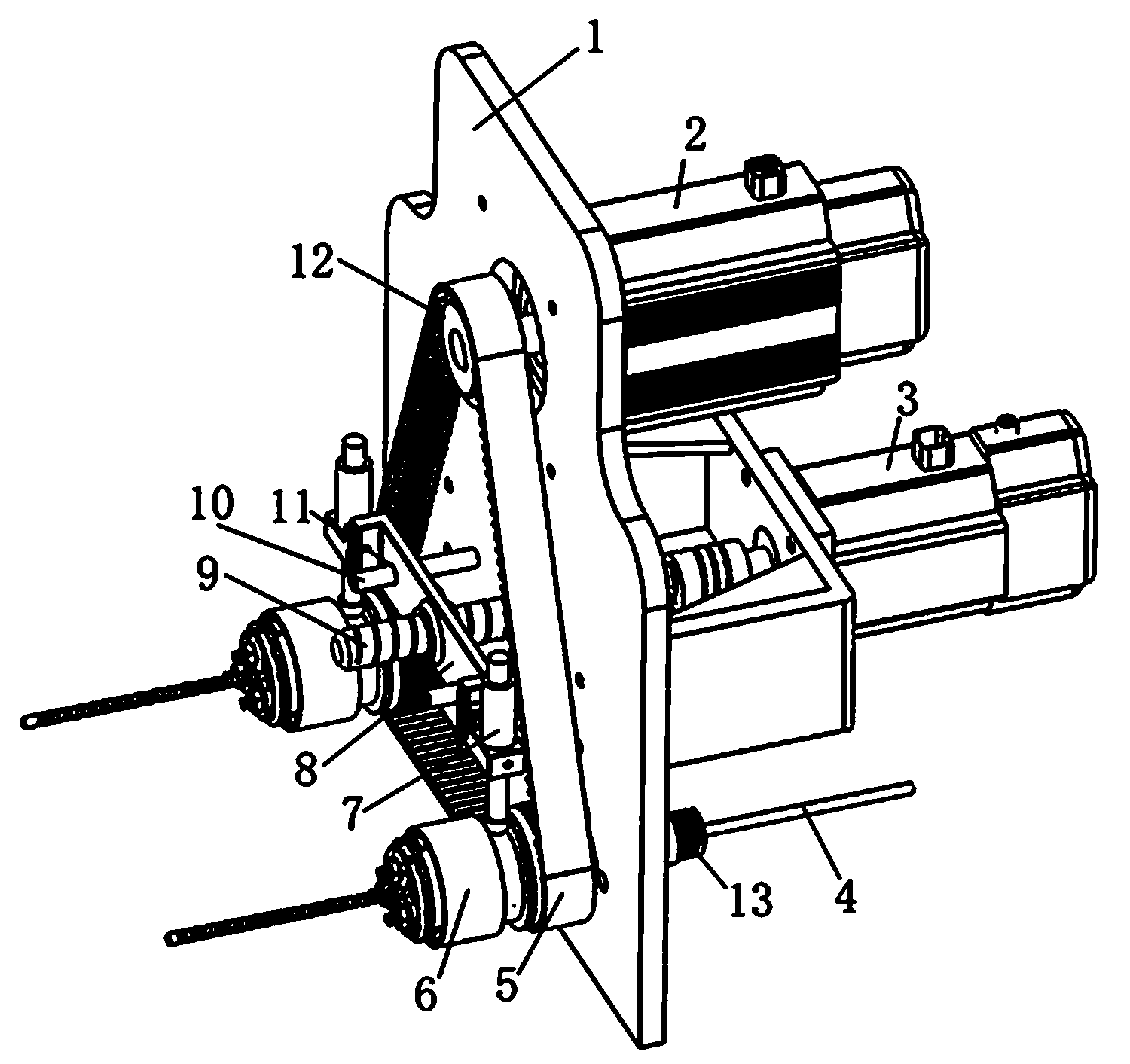
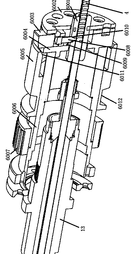
[0027] Such as figure 1 , figure 2 As shown, the head assembly of the pipe thread forming machine includes a bracket 1, two molding dies 6 arranged on the bracket 1 and their transmission devices. The molding die 6 includes a molding sleeve 6001 and a support frame 6004 set on the molding sleeve 6001. 1. Thread forming parts, the bracket 1 is respectively provided with hollow shafts 13 for installing two molding dies 6, the front surface of the support frame 6004 is provided with a stopper 6002, and the entrance end of the stopper 6002 corresponding to the forming sleeve 6001 is provided with Hollow hole, the rear end of the support frame 6004 is fixedly connected with a rotating support sleeve 6006, the rotating support sleeve 6006 is set on the hollow shaft 13 and rotates around it, the axis line of the hollow shaft 13 and the axis line of the forming sleeve 6001, and the support frame 6004 The axial lines of the hollow shaft 13 are coincident, and the aperture of the thro...
Embodiment 2
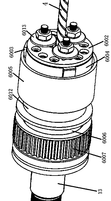
[0032] Such as Figure 3-Figure 5 As shown, in the present embodiment, three radial chute 6009 are evenly provided on the peripheral surface of the support frame 6004, and the wedge-shaped slider 6003 whose top surface is higher than the chute 6009 and slides along the chute 6009 is arranged in the chute 6009, and the thread forming part is The three rollers 6013 are symmetrically arranged on the front end of the block 6002 at a position corresponding to the slider 6003 at an angle of 120°, and the roller shafts 6016 of the three rollers 6013 respectively pass through the block 6002 and are connected to the side of the corresponding slider 6003. The sheet 6002 is provided with radial elongated holes 6015 corresponding to the roller shaft 6016 . Others are the same as embodiment 1.
[0033]The servo motor Ⅱ3 starts first, the lead screw 9 rotates, the lead screw 9 drives the shift fork frame 8 and the two shift forks 7 on it to slide forward, the shift fork 7 pushes the corres...
Embodiment 3
[0035] Such as Figure 6 As shown, in the present embodiment, three radial chute 6009 are uniformly provided on the peripheral surface of the support frame 6004, and the wedge-shaped slider 6003 whose top surface is higher than the chute 6009 and slides along the chute 6009 is arranged in the chute 6009. A roller 6013 and two bearings 6014 that are evenly distributed on the front end of the blocking piece 6002 along the circumferential direction corresponding to the position of the slider 6003 are formed. The shafts are respectively connected to the side of the corresponding slider 6003 through the blocking piece 6002, and the blocking piece 6002 is provided with a radial elongated hole 6015 corresponding to the roller shaft 6016 and the shaft of the bearing. Others are the same as embodiment 1.
[0036] The servo motor Ⅱ3 starts first, the lead screw 9 rotates, the lead screw 9 drives the shift fork frame 8 and the two shift forks 7 on it to slide forward, the shift fork 7 p...
PUM
 Abstract
Description
Claims
Application Information
 - R&D
- Intellectual Property
- Life Sciences
- Materials
- Tech Scout
- Unparalleled Data Quality
- Higher Quality Content
- 60% Fewer Hallucinations
Browse by: Latest US Patents, China's latest patents, Technical Efficacy Thesaurus, Application Domain, Technology Topic, Popular Technical Reports.
© 2025 PatSnap. All rights reserved.Legal|Privacy policy|Modern Slavery Act Transparency Statement|Sitemap|About US| Contact US: help@patsnap.com


