
System and method for preheating a heat recovery steam generator

A technology of steam generator and waste heat recovery, applied in the field of power generation

Inactive Publication Date: 2017-09-01
GENERAL ELECTRIC TECH GMBH
View PDF9 Cites 0 Cited by
  • Summary
  • Abstract
  • Description
  • Claims
  • Application Information

AI Technical Summary

Problems solved by technology

However, the gradual introduction of flue gas into the HRSG delays the combined cycle power plant from reaching full operating capacity

Method used


Image

  • System and method for preheating a heat recovery steam generator
  • System and method for preheating a heat recovery steam generator
  • System and method for preheating a heat recovery steam generator

Examples


Embodiment Construction

[0046] Reference will now be made in detail to the exemplary embodiments of the invention, examples of which are illustrated in the accompanying drawings. Wherever possible, the same reference numerals are used throughout the drawings to denote the same or similar parts without repeating description.

[0047] As used herein, the terms "substantially", "substantially" and "approximately" refer to a state within reasonably achievable manufacturing and assembly tolerances with respect to an ideal desired state suitable for achieving the functional purpose of a component or assembly. As used herein, "electrically coupled," "electrically connected," and "electrically communicating" means that the referred elements are directly or indirectly connected such that electrical current can flow from one to the other. Connections may include direct conductive connections (ie, without intervening capacitive, inductive, or active elements), inductive connections, capacitive connections, and / ...


PUM


Abstract

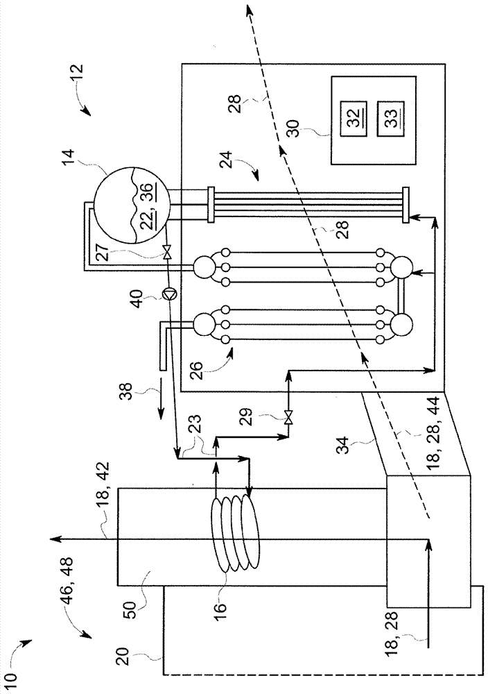
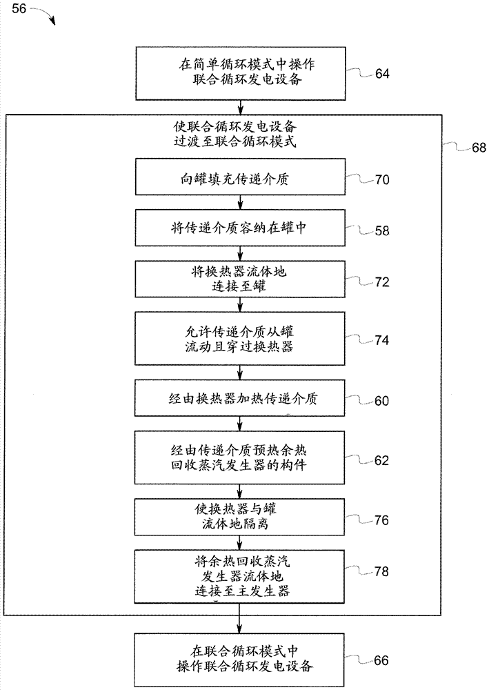
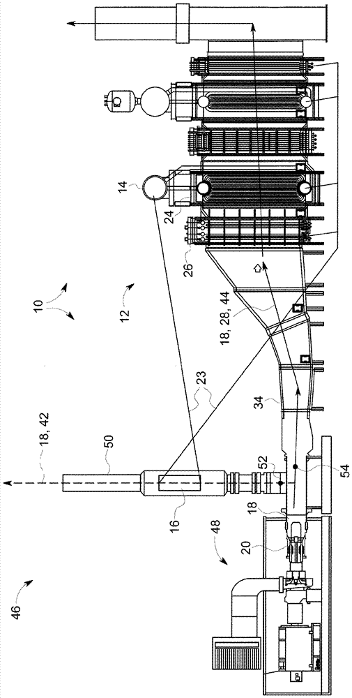
A system (10) for preheating a heat recovery steam generator (12) is provided. The system (10) includes a tank (14) and a heat exchanger (16). The tank (14) contains a transferring medium (22). The heat exchanger (16) is disposed in a flow path of a flue gas (18) produced by a combustion chamber (20), and is fluidly connected to the tank (14) such that the transferring medium (22) flows through the heat exchanger (16) and is heated by the flue gas (18). The transferring medium (22) preheats one or more components (14, 24, 26) of the heat recovery steam generator (12).

Description

technical field [0001] Embodiments of the present invention relate generally to power generation, and more particularly to systems and methods for preheating waste heat recovery steam generators. Background technique [0002] A heat recovery steam generator ("HRSG") is a device that recovers heat energy from a heat containing medium such as flue gas produced via fuel combustion, or any other gas and / or plasma containing recoverable heat energy. Many HRSGs recover heat from a heat-containing medium by exposing one or more components, usually a pressurized / pressure section such as an evaporator and / or a superheater, to the heat-containing medium. In this HRSG, the evaporator generates steam by absorbing / recovering some of the thermal energy from the heat containing medium. The superheater then dries the generated steam by absorbing / recovering more thermal energy from the heat containing medium. The dried steam is then typically distributed to a steam consumer, such as a stea...

Claims


Application Information

Patent Timeline
Patent Type & Authority Applications(China)
IPC IPC(8): F22B31/08F22D3/04
CPCF22B31/08F22D3/04F01K3/14F01K13/02F01K23/101F22B1/1815F28D21/0003Y02E20/16Y02E20/30F22B1/18F22B21/26F22B37/10F22G1/02F02C6/18F02G5/02F02G2254/15
Inventor R.R.努南W.P.鲍弗二世
Owner GENERAL ELECTRIC TECH GMBH
Learn More