Bridge girder erection machine capable of realizing on-girder whole-hole two-way erection of large-tonnage asymmetric different-width precast box girder

An asymmetric, large-tonnage technology, which is applied in the direction of erecting/assembling bridges, bridge construction, bridges, etc., can solve the problem of unstable erection of large-tonnage asymmetrical box girders, large-tonnage double-width box girders with many auxiliary facilities, and the inability to carry out double-width beams in one hole Problems such as erecting beams to achieve the effect of improving equipment operation efficiency, meeting erection requirements and safety, and ensuring stability

Pending Publication Date: 2017-09-01
CHINA RAILWAY NO 2 ENG GRP CO LTD +2
View PDF6 Cites 3 Cited by
  • Summary
  • Abstract
  • Description
  • Claims
  • Application Information

AI Technical Summary

Problems solved by technology

[0009] The purpose of the present invention is to overcome the complex structure of the bridge erecting machine existing in the prior art when the traditional bridge erecting machine erects large-tonnage prefabricated box girders, the inability to realize simple and efficient U-turn on the bridge, the inconvenience of erecting the first and last holes, and the overall There are many auxiliary facilities for the erection of large-tonnage double-width box girders, and the erection of large-tonnage asymmetrical box girders is unstable and cannot be erected with one hole and double-width girders. A simple disassembly and assembly on the bridge can realize two-way erection of beams, and the erection of the first and last holes is safe. It is a bridge erecting machine that is fast, convenient to change the span, and can directly erect the left and right large-tonnage asymmetrical prefabricated box girders on the girder.

Method used


Image

  • Bridge girder erection machine capable of realizing on-girder whole-hole two-way erection of large-tonnage asymmetric different-width precast box girder
  • Bridge girder erection machine capable of realizing on-girder whole-hole two-way erection of large-tonnage asymmetric different-width precast box girder
  • Bridge girder erection machine capable of realizing on-girder whole-hole two-way erection of large-tonnage asymmetric different-width precast box girder

Examples


Embodiment Construction

[0040] The present invention will be further described in detail below in conjunction with test examples and specific embodiments. However, it should not be understood that the scope of the above subject matter of the present invention is limited to the following embodiments, and all technologies realized based on the content of the present invention belong to the scope of the present invention.

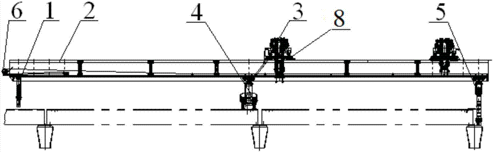
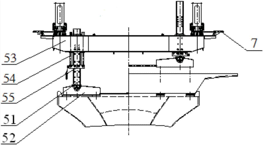
[0041] Such as Figure 1-2 As shown, a bridge erecting machine that can realize the two-way erection of the whole hole on the large-tonnage asymmetric framed prefabricated box girder includes a machine arm 2 designed symmetrically along the longitudinal and transverse directions, and the front arm 2 is provided with The outrigger 5, the middle outrigger 4 and the rear outrigger 1, the front outrigger 5, the middle outrigger 4 and the rear outrigger 1 are respectively connected with the machine arm 2 through a latch locking device 7, so The front and rear trolleys 8 that run longitud...


PUM


Abstract

The invention discloses a bridge girder erection machine capable of realizing on-girder whole-hole two-way erection of a large-tonnage asymmetric different-width precast box girder. The bridge girder erection machine comprises a machine arm in symmetric design in longitudinal and transverse directions, wherein a front support leg, a middle support leg and a back support leg are arranged on the machine arm, front and back trusses travelling along a girder longitudinally are arranged on the machine arm, front and back crane trolleys capable of moving leftwards and rightwards as well as a winch supporting and pulling mechanism for longitudinal traveling of each support leg are arranged on the trusses, the front support leg can be moved and realize multi-stage telescoping, lifting appliances adopted by the crane trolleys comprise shoulder pole beams and multiple roe piece assemblies, transverse balancing devices are arranged at the upper ends of the shoulder pole beams, and stepless adjustment devices and longitudinal swing adjustment devices are arranged on two sides. The bridge girder erection machine adopts a three-support-leg structure without a front auxiliary support leg, during span change, the front support leg travels longitudinally to the corresponding span position, positioning pins are inserted, and thus, span change of the whole machine can be realized; the bridge girder erection machine can erect the girder reversely after the front and back support legs are interchanged quickly and simply on the bridge.

Description

technical field [0001] The invention relates to a bridge erecting machine, in particular to a bridge erecting machine capable of realizing two-way erection of a whole hole on a prefabricated large-tonnage asymmetric framed box girder. Background technique [0002] Large-scale frame transport equipment is used to realize the construction method of transporting beams on beams on beams and erecting whole holes of bridge erecting machines. It has the advantages of reliable quality, high efficiency, and less impact on traffic and the environment. In the existing railway engineering, the construction method of transporting the girder on the large-tonnage prefabricated box girder girder and erecting a piece of box girder through the whole hole of the bridge erecting machine has been widely used. In highway engineering, only the Hangzhou Bay Bridge has carried out the construction of large-tonnage prefabricated box girder girders. Through various auxiliary facilities, its bridge ere...

Claims


Application Information

Patent Timeline
Patent Type & Authority Applications(China)
IPC IPC(8): E01D21/00
CPCE01D21/00
Inventor 熊国辉王心利李珍西李世龙申超袁宝成向锐胡勇彭程陈家乐
Owner CHINA RAILWAY NO 2 ENG GRP CO LTD
Why Eureka
Try Eureka