
Device with tool head capable of being dismounted conveniently

A technology for dismantling tools and tool heads, which is applied to devices for fixing grinding wheels, manufacturing tools, metal processing equipment, etc., can solve problems such as danger and inconvenience, and achieve the effect of not being easy to disassemble, simple in structure, and easy to implement

Inactive Publication Date: 2017-09-01
SUZHOU SPARKS PRECISION MACHINERY CO LTD
View PDF0 Cites 0 Cited by
  • Summary
  • Abstract
  • Description
  • Claims
  • Application Information

AI Technical Summary

Problems solved by technology

In the prior art, the disassembly of the tool head of the cylindrical grinding machine tool, that is, the cutter head, needs to enter the entire working chamber to disassemble the grinding wheel, which is very inconvenient and has certain dangers

Method used


Image

  • Device with tool head capable of being dismounted conveniently

Examples


Embodiment Construction

[0012] The present invention will be described in detail below in conjunction with the accompanying drawings and specific embodiments.

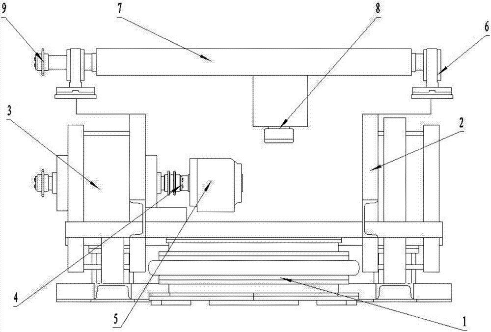
[0013] Such as figure 1 As shown, the present invention is a device for conveniently dismounting the tool head, which is composed of a base 1, a support column 2, a headstock 3, a rotating shaft 4, a chuck 5, a bearing seat 6, a crossbeam 7 and a grinding wheel tool head 8. The above-mentioned base 1 is fixedly provided with a supporting column 2, and the upper part of the supporting column 2 is provided with a bearing seat 6, and a crossbeam 7 is connected between the bearing seats 6, and a chute is arranged at the bottom of the crossbeam 7, and the chute is movably connected with the grinding wheel tool head 8 , One side of the upper part of the base 1 is provided with a headstock 3, and the headstock 3 is connected to the chuck 5 through the rotating shaft 4.

[0014] Described chute is a kind of I-shaped groove.

[0015] Buckles are arr...


PUM


Abstract

The invention discloses a device for conveniently disassembling a tool head, which is composed of a base, a support column, a spindle box, a rotating shaft, a chuck, a bearing seat, a beam and a grinding wheel tool head, and the support column is fixedly arranged on the base, The upper part of the support column is provided with a bearing seat, and the beam is connected between the bearing seats. A chute is provided at the lower part of the beam, and the chute is movably connected with the grinding wheel tool head. The upper side of the base is provided with a headstock, and the headstock is connected by a rotating shaft. Chuck. The invention has a simple structure, is easy to implement, and effectively solves the problem that the tool head of a traditional machine is not easy to disassemble.

Description

technical field [0001] The invention relates to a grinding wheel device, in particular to a device for conveniently dismounting a tool head. Background technique [0002] Cylindrical grinding is mainly carried out on the cylindrical grinding machine, which is used to grind the outer cylinder, outer cone and shaft shoulder end face of the shaft workpiece. During grinding, the workpiece rotates at a low speed. If the workpiece is reciprocated longitudinally at the same time and the grinding wheel is fed laterally relative to the workpiece after each single or double stroke of longitudinal movement, it is called longitudinal grinding method. If the width of the grinding wheel is greater than the length of the surface to be ground, the workpiece does not move longitudinally during the grinding process, but the grinding wheel is continuously fed laterally relative to the workpiece, which is called the plunge grinding method. Generally, the plunge grinding method is more efficien...

Claims


Application Information

Patent Timeline
IPC IPC(8): B24B45/00
CPCB24B45/00B24B45/003
Inventor 曹乐
Owner SUZHOU SPARKS PRECISION MACHINERY CO LTD
Learn More