
A method for constructing a net cage floating pipe frame

A construction method and floating tube technology, applied in the field of cage culture, can solve the problems of high time cost, rudimentary and poor connection, difficulty in launching the cage, etc., and achieve the effect of solving the difficult site

Active Publication Date: 2019-08-30
SOUTH CHINA SEA FISHERIES RES INST CHINESE ACAD OF FISHERY SCI
View PDF1 Cites 0 Cited by
  • Summary
  • Abstract
  • Description
  • Claims
  • Application Information

AI Technical Summary

Problems solved by technology

The whole process is not very technical, but due to the scattered, crude and poor connection of construction tools, and the lack of other auxiliary machinery, 80% of the work is done by manpower, so it is still relatively low-end and extensive construction, and the quality is not high. and inefficient
[0005] 3. Cage launch: Due to the limitation of the site, even if the selected site is as close to the sea as possible, it is still very difficult to launch the completed cage, whether it is external auxiliary machinery such as forklifts, loaders, excavators, cranes, etc. The special machinery and equipment are still purely manpower, and they are basically pulled into the water by force. During the process, there have been many accidents where the floating pipe was overloaded and broken; at the same time, the random selection of the site, the inclusion of large, sharp stones or other sharp debris is inevitable, and the cages are used. In the process of pulling and pulling into the water, accidents of surface scratches frequently occur; launching into the water often needs to wait for high tide and high water level, and the time cost is high, which brings obstacles to the organization of the next construction
At the same time, due to the geographical factors of the site, if you want to hire auxiliary machinery and equipment, you often need to pay high fees, so the capital cost, time cost and quality cost are very high, and the cost is very high.

Method used


Image

  • A method for constructing a net cage floating pipe frame
  • A method for constructing a net cage floating pipe frame
  • A method for constructing a net cage floating pipe frame

Examples


Embodiment 1

[0066] Such as Figure 9 As shown, Embodiment 1 of the present invention is based on the above-mentioned inventive concepts, and adopts the following preferred solutions:

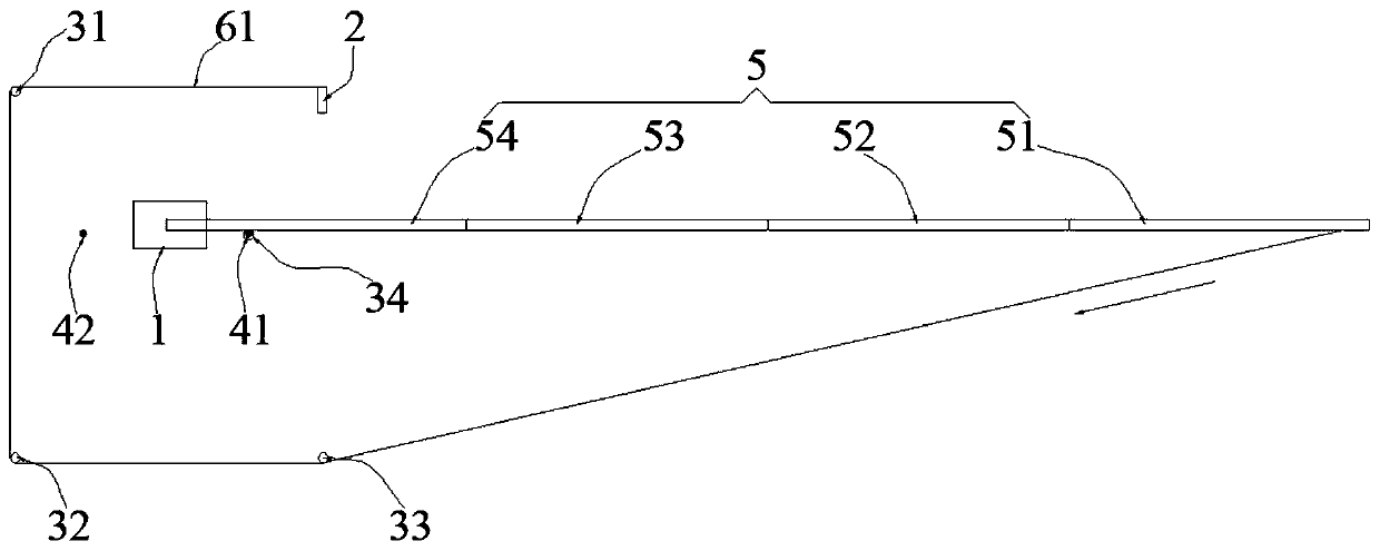
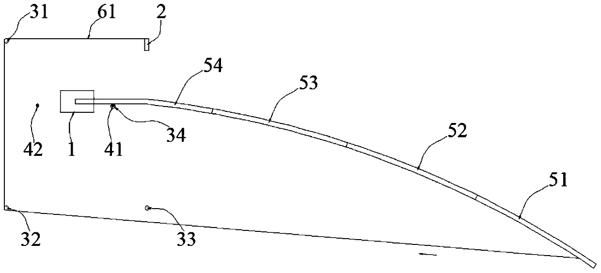
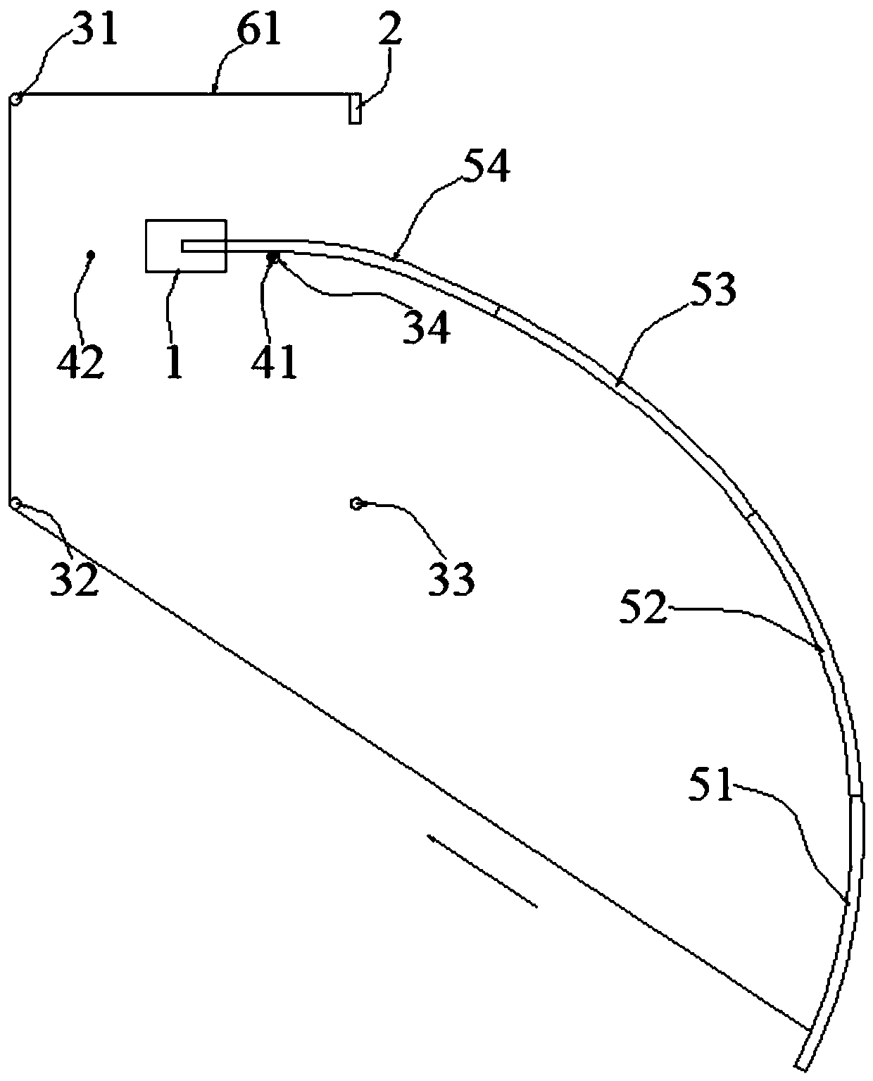
[0067] In order to ensure that the outer end of the linear floating pipe 5 used for construction in step 4 can stretch into the slips of the heat fusion welding machine 1 along the direction from the second stop post 42 to the first stop post 41, reduce the construction cost. The impact of the elastic force of the linear floating pipe 5 itself on this process is to realize the docking of the two ports of the linear floating pipe 5 for construction. Positioning column 44; the third limiting column 43 and the fourth limiting column 44 are relatively fixed with the position of the first limiting column 41 and are all located in the quadrangular area, and the third limiting column 43 is close to the third guide roller 33 Setting, the fourth limit post 44 is set close to the second guide roller 32;

[0068] In...

Embodiment 2

[0070] Such as Figures 10 to 12 As shown, Embodiment 2 of the present invention is basically the same as Embodiment 1 above, and their difference lies in:

[0071] The net cage floating pipe frame construction method of the second embodiment of the present invention is also implemented based on the platform 7 floating on the water surface, and the net cage floating pipe frame construction device is installed on the platform 7; The size of the facilities and platform 7 will be finally determined based on factors such as the size of the construction net cage, the number of net cages (considering how much material needs to be prepared), the size of the rest and living area of ​​the operator, and its layout is set as a material stacking area and a welding area according to the requirements of the new technology. area and bending forming area, the platform itself has functions such as power supply equipment or connection to shore power devices, and can be used for workers to rest ...

Embodiment 3

[0076] Such as Figure 13 As shown, Embodiment 3 of the present invention can be implemented based on Embodiment 1 or Embodiment 2 above, and their differences are:

[0077] In step one of Embodiment 3 of the present invention, the linear floating pipe 5 for construction is welded sequentially by multiple standard linear floating pipes with equal lengths, and the welding method of any two adjacent standard linear floating pipes is as follows: : Firstly, fix the inner end of the previous section of the standard straight line floating pipe and the outer end of the next standard straight line floating pipe in the slips of the heat fusion welding machine 1, and the previous section of the standard straight line The inner end nozzle of the type floating pipe is connected with the outer end nozzle of the standard straight line floating pipe in the next section, and then the inner end of the standard straight line floating pipe in the previous section is connected with a hot-melt wel...


PUM


Abstract

The invention discloses a net cage floating pipe framework construction method. The net cage floating pipe framework construction method is implemented on the basis of a net cage floating pipe framework construction device, the net cage floating pipe framework construction device is provided with a hot melting machine, a winch, four guide rollers, a first limiting column and a second limiting column with relatively fixed positions; and the construction method comprises: coiling a first cable wire and a second cable wire by the winch in sequence, and accomplishing butt welding by using the hot melting machine to construct a net cage floating pipe framework. Therefore, by virtue of the net cage floating pipe framework construction method disclosed by the invention, the automation degree of net cage floating pipe framework construction is greatly improved, the manpower resources necessary for the net cage floating pipe framework construction are reduced, and the construction quality of the net cage floating pipe framework is improved.

Description

technical field [0001] The invention relates to a method for constructing a net cage floating pipe frame, and belongs to the technical field of net cage culture. Background technique [0002] In recent years, my country's cage aquaculture industry has developed rapidly. While achieving remarkable results, many new problems have been exposed. Taking the construction of cages as an example, the traditional construction methods have extremely mismatched with the needs of the rapidly developing industry. The main manifestations are: [0003] 1. In terms of construction site: the beach is temporarily selected, the site is mainly rented, or the site is temporarily opened up. The selection is random and basically does not have the levelness or flatness required for construction, resulting in some joints in the welding process of the net cage. Coaxial (not straight) brings quality hidden dangers; Also produces a large amount of manpower to move, carry, lift, pull, pad etc. work in t...

Claims


Application Information

Patent Timeline
Patent Type & Authority Patents(China)
IPC IPC(8): A01K61/60
CPCA01K61/60Y02A40/81
Inventor 王绍敏陶启友刘海阳郭根喜黄小华胡昱
Owner SOUTH CHINA SEA FISHERIES RES INST CHINESE ACAD OF FISHERY SCI
Learn More