Pump unit for feeding fuel, preferably diesel fuel, to an internal combustion engine

A pump unit, internal combustion engine technology, applied in the direction of fuel injection pumps, components of pumping devices for elastic fluids, liquid fuel engines, etc., can solve the problems of costly precision machining operations, wear and sealing, and achieve easy threaded connections Realize, reduce friction and wear points, reduce wear effect

Active Publication Date: 2017-08-29
ROBERT BOSCH GMBH
View PDF9 Cites 2 Cited by
  • Summary
  • Abstract
  • Description
  • Claims
  • Application Information

AI Technical Summary

Problems solved by technology

[0004] A major disadvantage of the prior art is the rather long and costly precision machining operation required to form the threaded surface on the inside wall of the base
Furthermore, said threaded surfaces thus formed can lead to wear and tightness problems during the working life of the pump, since they have to withstand high forces

Method used


Image

  • Pump unit for feeding fuel, preferably diesel fuel, to an internal combustion engine
  • Pump unit for feeding fuel, preferably diesel fuel, to an internal combustion engine
  • Pump unit for feeding fuel, preferably diesel fuel, to an internal combustion engine

Examples


Embodiment Construction

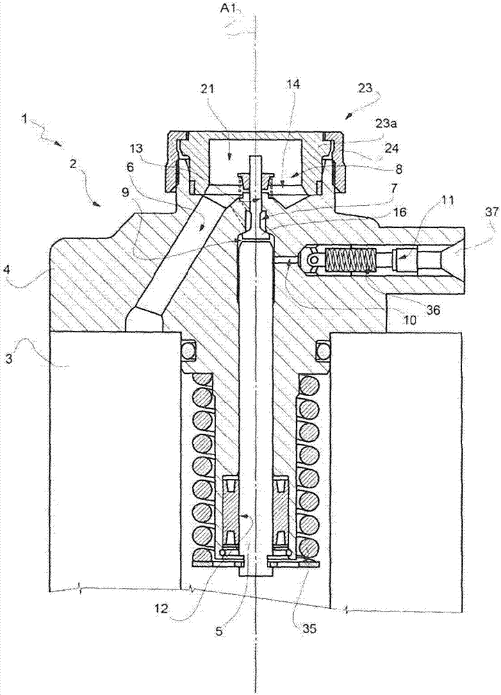
[0039] refer to figure 1 and figure 2 , reference number 1 designates as a whole a pump unit for supplying fuel, preferably diesel, to an internal combustion engine (not shown).

[0040] The pump unit 1 comprises: a high-pressure pump 2 of the pumping piston type, designed to supply fuel to said internal combustion engine (not shown); and a known gear pump (not shown), which Designed to feed fuel to pump 2. The pump 2 and the gear pump are driven by shafts (not shown in the figures).

[0041] The pump 2 comprises: a pump body 3; a head 4 assembled on the pump body 3; a cylinder 12 formed in the head 4 and extending along the axis A1; a pumping piston 5 extending along the axis A1, And with the cylinder 12 slidingly coupled; feed pipe 6, which is partially formed in the head 4; feed valve 7, which communicates with the feed pipe 6; feed chamber 8, which is arranged in the feed pipe 6 and the inlet valve 7; the compression chamber 9, which communicates with the inlet chambe...


PUM


Abstract

A pump unit for feeding fuel, preferably diesel fuel, to an internal combustion engine; the pump unit (1) comprising: a head (4) inside which a cylinder (12) extending along an axis (A1) is formed; a pumping piston (5) extending along the axis (A1) and slidingly coupled with the cylinder (12); a through-hole (13) which extends from the cylinder (12) towards the outside of the pump unit (1); an intake chamber (8) communicating with the cylinder (12) via the hole (13); an intake valve (7) which controls the flow of fuel from the intake chamber (8) to the hole (13); a cap (23; 123; 223) which is connected to the head (4), is arranged on the opposite side to the pumping piston (5) and can be selectively fixed along an outer surface (25) of the head (4) so as to close the intake chamber (8) on one side.

Description

technical field [0001] The invention relates to a pump unit for supplying fuel, preferably diesel, to an internal combustion engine. Background technique [0002] Generally, a pump unit comprises: a pump body; a head assembled on the pump body; a pumping piston accommodated in the head; a cylinder housing the pumping piston; an inlet valve with a valve body housing within a base formed in the head; and a delivery valve. [0003] The valve body is secured to the base by means of threaded means which fit the inner wall of the base. In particular, the pump body includes a connector having a threaded outer surface that is received within the seat after the valve body is inserted. The connector keeps the valve body in contact with the head. The connector is secured to the inside surface of the base by means of a threaded connection through a threaded surface formed on the threaded outside wall of the connector and a strap formed on the inside wall of the base. threaded surfac...

Claims


Application Information

Patent Timeline
Patent Type & Authority Applications(China)
IPC IPC(8): F02M59/06F02M59/10F02M59/46
CPCF02M59/06F02M59/102F02M59/464F04B1/0421F04B1/0452F04B1/0456F04B53/12F04B53/16
Inventor B·洛亚科诺M·A·扬努齐L·莫斯卡雷拉D·马基亚
Owner ROBERT BOSCH GMBH
Why Eureka
Try Eureka