A flat gate valve with refractory function
A flat gate valve, functional technology, applied in valve device, valve details, sliding valve and other directions, can solve the problems of poor flame retardant effect, no high temperature resistance effect, etc., to achieve the effect of improving sealing
- Summary
- Abstract
- Description
- Claims
- Application Information
AI Technical Summary
Problems solved by technology
Method used
Image

Examples
Embodiment 1
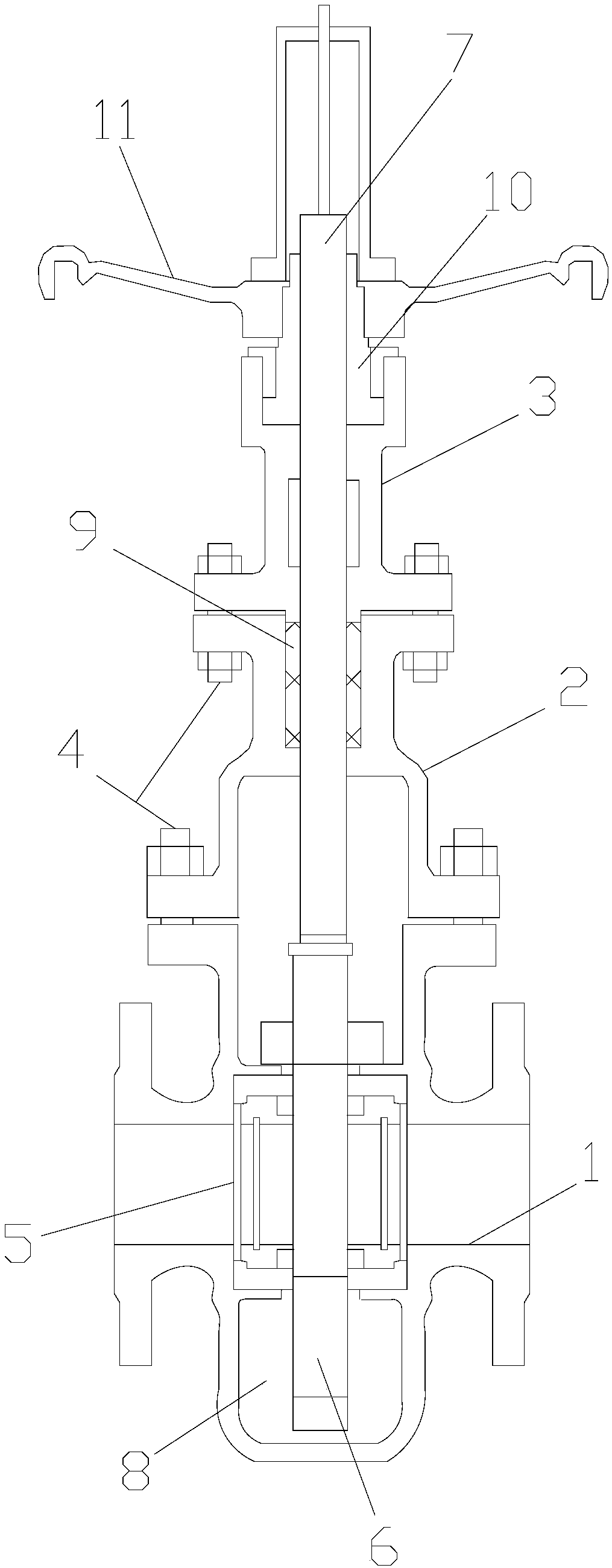
[0023] A slab gate valve with a fire-resistant function, comprising a valve body 1, a valve cover 2 and a top cover 3, the valve body 1, the valve cover 2 and the top cover 3 are sequentially arranged from bottom to top, the valve body 1 and the valve cover 2 The two are fixed by bolts 4, the top cover 3 and the valve cover 2 are fixed by bolts, a valve seat 5 is installed in the valve body 1, a valve plate 6 is installed in the valve seat 5, and the valve plate 6 is clamped with the valve seat 5, the top of the valve plate 6 is fixed with a valve stem 7, the bottom of the valve body 1 is provided with an accommodation cavity 8, and the valve stem 7 passes through the valve cover 2 and the top cover 3 in turn, the A filler 9 is filled between the top of the valve cover 2 and the valve stem 7 , and sealing grease is injected into the filler 9 , a stem nut 10 is installed on the top of the valve stem 7 , and a handwheel 11 is fixed outside the stem nut 10 . The valve plate is ma...
Embodiment 2
[0033] A slab gate valve with a fire-resistant function, comprising a valve body 1, a valve cover 2 and a top cover 3, the valve body 1, the valve cover 2 and the top cover 3 are sequentially arranged from bottom to top, the valve body 1 and the valve cover 2 The two are fixed by bolts 4, the top cover 3 and the valve cover 2 are fixed by bolts, a valve seat 5 is installed in the valve body 1, a valve plate 6 is installed in the valve seat 5, and the valve plate 6 is clamped with the valve seat 5, the top of the valve plate 6 is fixed with a valve stem 7, the bottom of the valve body 1 is provided with an accommodation cavity 8, and the valve stem 7 passes through the valve cover 2 and the top cover 3 in turn, the A filler 9 is filled between the top of the valve cover 2 and the valve stem 7 , and sealing grease is injected into the filler 9 , a stem nut 10 is installed on the top of the valve stem 7 , and a handwheel 11 is fixed outside the stem nut 10 . The valve plate is ma...
Embodiment 3
[0043] A slab gate valve with a fire-resistant function, comprising a valve body 1, a valve cover 2 and a top cover 3, the valve body 1, the valve cover 2 and the top cover 3 are sequentially arranged from bottom to top, the valve body 1 and the valve cover 2 The two are fixed by bolts 4, the top cover 3 and the valve cover 2 are fixed by bolts, a valve seat 5 is installed in the valve body 1, a valve plate 6 is installed in the valve seat 5, and the valve plate 6 is clamped with the valve seat 5, the top of the valve plate 6 is fixed with a valve stem 7, the bottom of the valve body 1 is provided with an accommodation cavity 8, and the valve stem 7 passes through the valve cover 2 and the top cover 3 in turn, the A filler 9 is filled between the top of the valve cover 2 and the valve stem 7 , and sealing grease is injected into the filler 9 , a stem nut 10 is installed on the top of the valve stem 7 , and a handwheel 11 is fixed outside the stem nut 10 . The valve plate is ma...
PUM
 Abstract
Description
Claims
Application Information
 - R&D
- Intellectual Property
- Life Sciences
- Materials
- Tech Scout
- Unparalleled Data Quality
- Higher Quality Content
- 60% Fewer Hallucinations
Browse by: Latest US Patents, China's latest patents, Technical Efficacy Thesaurus, Application Domain, Technology Topic, Popular Technical Reports.
© 2025 PatSnap. All rights reserved.Legal|Privacy policy|Modern Slavery Act Transparency Statement|Sitemap|About US| Contact US: help@patsnap.com