Color projection display optical engine
A projection display and optical engine technology, applied in the field of optical engines, can solve the problems of low optical efficiency, small pixel size, difficult high-resolution display, etc., and achieve the effects of high resolution, improved brightness, and good color reproduction.
- Summary
- Abstract
- Description
- Claims
- Application Information
AI Technical Summary
Problems solved by technology
Method used
Image

Examples
Embodiment 1
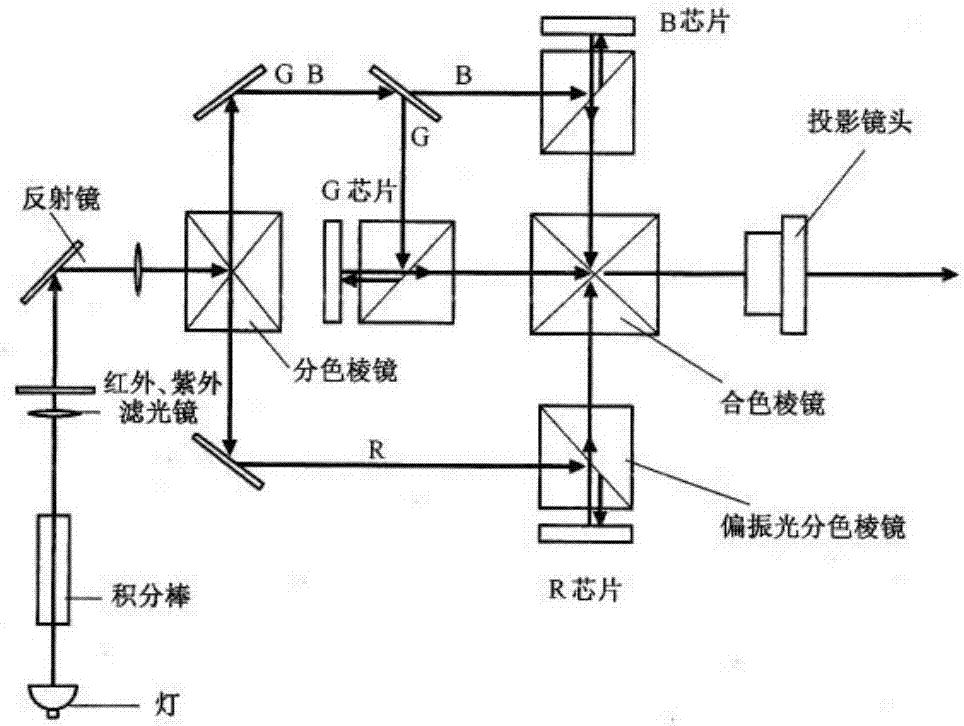
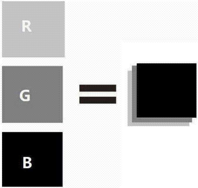
[0027] The structure of the existing three-chip projection optical engine is as follows: figure 1 As shown, the white light source is divided into three colors of R, G, and B through a dichroic prism, and then irradiated on three LCOSs through a polarizing beam splitter (PBS). The color combination prism mixes the images of the three colors into a full-color picture, which is projected out through the lens system for imaging. This kind of optical engine needs to use multiple display devices, the process is complicated, the cost is high, and it is not easy to miniaturize. At the same time, because the three pieces are displayed as a discrete structure, because of assembly deviation, there are registration problems in the synthesis of red, green and blue reproduced images in space, which is prone to color alignment deviation, such as figure 2 shown.
[0028] The color projection display optical engine disclosed by the present invention is as image 3 As shown, it includes an...
Embodiment 2
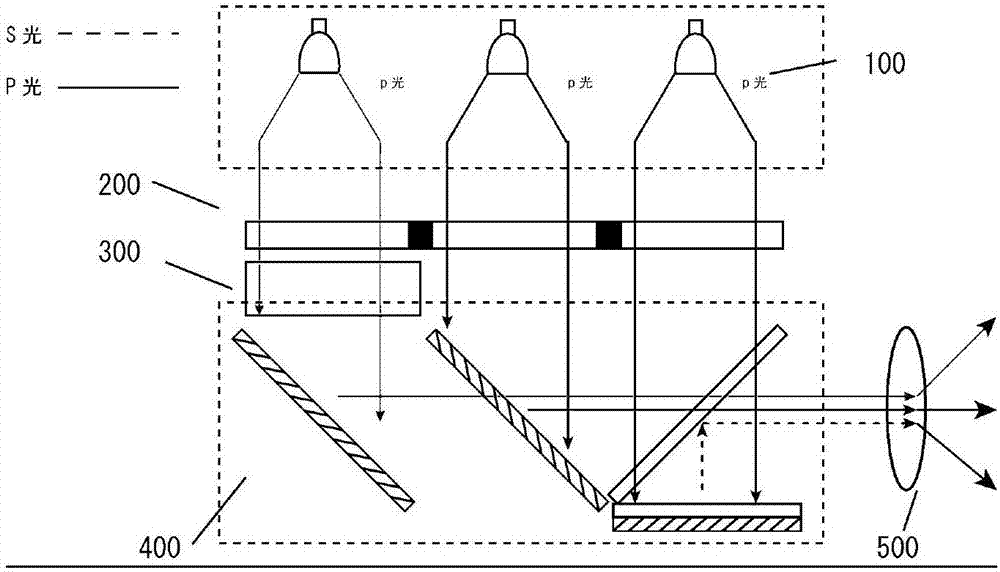
[0035] The color projection display optical engine disclosed in this embodiment is as Figure 8 As shown, it includes an illumination unit 100 , a display chip 200 , optical fiber image sensors 301 , 302 , a color combining unit 400 , and an imaging lens 500 .
[0036] As a preferred solution of the present invention, the lighting unit 100 of the optical engine is composed of three independent LED light sources of red 101, green 102, and blue 103, and the three kinds of monochromatic light sources pass through compound parabolic concentrators CPC 104, 105 , 106 collimated to obtain three kinds of monochromatic quasi-parallel light sources, which are vertically irradiated on the display chip 200. The display chip adopts a transmissive liquid crystal display, including three independent display areas, which are the area 201 for modulating red light and the area 201 for green light modulation. For the light modulation area 202 and the blue light modulation area 203, each display ...
Embodiment 3
[0044] The color projection display optical engine disclosed in this embodiment is as Figure 10 As shown, it includes an illumination unit 100 , a display chip 200 , optical fiber image sensors 301 , 302 , a color combining unit 400 , and an imaging lens 500 .
[0045] As a preferred solution of the present invention, the lighting unit 100 of the optical engine is composed of three independent LED light sources of red 101, green 102, and blue 103, and the three kinds of monochromatic light sources pass through compound parabolic concentrators CPC 104, 105 , 106 collimated to obtain three kinds of monochromatic quasi-parallel light sources, which are vertically irradiated on the display chip 200. The display chip adopts a transmissive liquid crystal display, including three independent display areas, which are the area 201 for modulating red light and the area 201 for green light modulation. For the light modulation area 202 and the blue light modulation area 203, each display...
PUM
 Abstract
Description
Claims
Application Information
 - Generate Ideas
- Intellectual Property
- Life Sciences
- Materials
- Tech Scout
- Unparalleled Data Quality
- Higher Quality Content
- 60% Fewer Hallucinations
Browse by: Latest US Patents, China's latest patents, Technical Efficacy Thesaurus, Application Domain, Technology Topic, Popular Technical Reports.
© 2025 PatSnap. All rights reserved.Legal|Privacy policy|Modern Slavery Act Transparency Statement|Sitemap|About US| Contact US: help@patsnap.com