A boost inverter
An inverter and boost inductor technology, applied in the field of power electronic converters, can solve the problems of low conversion efficiency, high-frequency leakage current, etc., and achieve the effects of improving efficiency, reducing switching loss and simple structure
- Summary
- Abstract
- Description
- Claims
- Application Information
AI Technical Summary
Problems solved by technology
Method used
Image

Examples
Embodiment 1
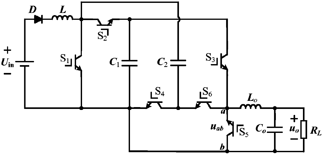
[0042] Such as figure 1 As shown, a boost inverter in this embodiment, the power supply U in The anode of the diode D is connected to the anode of the diode, U in The cathode of the diode D is connected to one end of the boost inductor L, and the other end of the boost inductor L is connected to the switch tube S 1 The first end of the switch tube S 2 The first terminal and the capacitor C2 One end of the connection, the switch tube S 1 The second terminal of the ground, the capacitor C 2 The other end of the switch tube S 4 The first end of the switch and the switch S 6 connected to the second end of the switch tube S 4 The second end of the ground. Switch tube S 2 The second terminal and the capacitor C 1 One end of the switch and the switch S 3 connected to the first end of the capacitor C 1 The other end of the ground, the switch tube S 3 The second end of the switch tube S 6 The first end of the switch tube S 5 connected to the second end of the switch tube ...
Embodiment 2
[0045] to combine figure 1 , a boost inverter in this embodiment, the power supply U in The anode of the diode is connected to the anode of the diode D, U in The cathode of the diode D is connected to one end of the boost inductor L, and the other end of the boost inductor L is connected to the switch tube S 1 The first end of the switch tube S 2 The first terminal and the capacitor C 2 One end of the connection, the switch tube S 1 The second terminal of the ground, the capacitor C 2 The other end of the switch tube S 4 The first end of the switch and the switch S 6 connected to the second end of the switch tube S 4 The second end of the ground. Switch tube S 2 The second terminal and the capacitor C 1 One end of the switch and the switch S 3 connected to the first end of the capacitor C 1 The other end of the ground, the switch tube S 3 The second end of the switch tube S 6 The first end of the switch tube S 5 connected to the second end of the switch tube S ...
Embodiment 3
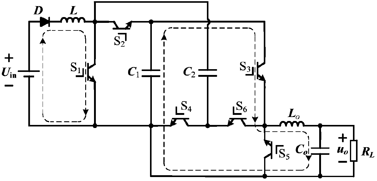
[0047] This embodiment combines Figure 2-8 Any technical scheme is analyzed in embodiment 1-2.
[0048] 3.1 Boost ratio analysis
[0049] Such as figure 1 shown, the capacitor C 1 、C 2 Share a boost inductor L, under the joint action of DC input power, C 1 、C 2 The energy storage is realized. Under the conditions of different switch combinations, the capacitance C 1 、C 2 Discharge to the output side, the front end of the filter can obtain the polar SPWM waveform voltage, and then through the freewheeling of the switch tube, the inverter process is finally realized. Among them, the function of the diode D is to ensure that the energy can only flow in one direction from the DC power supply to the load, and prevent the load energy from being fed back to the input side.
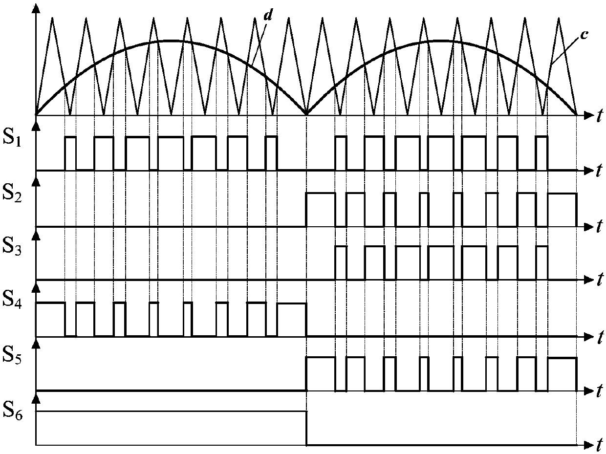
[0050] The switching tube modulation strategy is shown in 2. The modulation wave is the absolute value of the sine wave, compared with the triangular wave carrier to obtain the PWM wave, as the switch t...
PUM
 Abstract
Description
Claims
Application Information
 - R&D
- Intellectual Property
- Life Sciences
- Materials
- Tech Scout
- Unparalleled Data Quality
- Higher Quality Content
- 60% Fewer Hallucinations
Browse by: Latest US Patents, China's latest patents, Technical Efficacy Thesaurus, Application Domain, Technology Topic, Popular Technical Reports.
© 2025 PatSnap. All rights reserved.Legal|Privacy policy|Modern Slavery Act Transparency Statement|Sitemap|About US| Contact US: help@patsnap.com