
A method and system for separating multiple partial discharge sources inside a transformer

A separation method and discharge source technology, applied in the direction of instruments, measuring electricity, measuring electrical variables, etc., can solve the problems of original signal distortion, complex transformer structure, complex partial discharge signal transmission path, etc., and achieve high separation accuracy and structural adaptability. Good performance, overcoming the effect of complex structure

Active Publication Date: 2019-11-08
STATE GRID CORP OF CHINA +2
View PDF3 Cites 0 Cited by
  • Summary
  • Abstract
  • Description
  • Claims
  • Application Information

AI Technical Summary

Problems solved by technology

[0004] The technical problem to be solved by the present invention: Aiming at the above-mentioned problems in the prior art, it is necessary to provide a multi-discharge power supply that can overcome the problems of complex transformer structure, complex partial discharge signal transmission path, and serious original signal distortion, and realize multi-discharge power supply for complex structural equipment such as transformers. Separation and identification, a separation method and system for multiple partial discharge sources inside a transformer with good structural adaptability and high separation accuracy

Method used


Image

  • A method and system for separating multiple partial discharge sources inside a transformer
  • A method and system for separating multiple partial discharge sources inside a transformer
  • A method and system for separating multiple partial discharge sources inside a transformer

Examples


Embodiment Construction

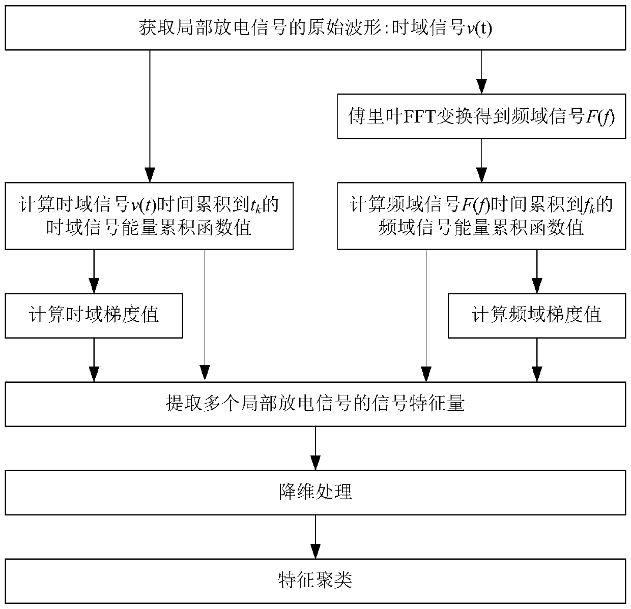
[0046] Such as figure 1 As shown, the steps of the method for separating multiple partial discharge sources inside the transformer in this embodiment include:

[0047] 1) Obtain the original waveform of partial discharge signals of multiple partial discharge sources inside the transformer;

[0048] 2) Perform Fourier FFT transform on the time-domain signal v(t) of the original waveform to obtain the frequency-domain signal F(f); respectively calculate the time-domain signal v(t) time for the time-domain signal v(t) based on the energy accumulation function accumulated to t k The value of the energy accumulation function of the time domain signal, based on the energy accumulation function for the frequency domain signal F(f) to calculate the frequency domain signal F(f) time accumulation to f k The frequency domain signal energy accumulation function value of ;

[0049] 3) Carrying out the mathematical form gradient calculation for the time-domain signal energy accumulation ...


PUM


Abstract

The invention discloses a method and system for separating partial discharge sources in a transformer. The method comprises the steps that the original waveform of partial discharge signals is obtained, and frequency domain signals are obtained from time domain signals; energy accumulated function values of the frequency domain signals and the time domain signals are calculated respectively, and mathematical-morphology gradient calculation is carried out on the frequency domain signals and the time domain signals; and the signal characteristic quantity is extracted on the basis of the energy accumulated function values and the gradient values, dimension reducing and characteristic clustering are carried out successively, and multiple separated partial discharge sources are obtained. The system comprises a waveform obtaining program module, an accumulated function calculating program module, a gradient calculating program module, a characteristic quantity extracting program module, a characteristic quantity dimension reducing program module and a clustering program module. According to the invention, the problems that the transformer structure is complex, transmission paths of the partial discharge signals are complexes and original signals distort seriously are overcome, the multiple discharge sources of equipment, as the transformer, of complex structure can be separated and identified, and the method and system have the advantages of high structural adaptability and high separating accuracy.

Description

technical field [0001] The invention relates to a multi-partial discharge signal detection technology of a power grid, in particular to a method and system for separating multi-partial discharge sources inside a transformer. Background technique [0002] The transformer is one of the core equipment of the power grid, and its stable and reliable operation will be of great significance to the power system. Due to limitations in design, manufacturing, technology, and operation and maintenance levels or system failures, transformer damage occurs from time to time. Statistics show that with the rapid development of the power grid, the short-circuit capacity of the power system increases, and the hidden dangers caused by external disturbances to the transformer are increasing. The transformer winding is prone to deformation, which may cause partial discharge after deformation. Under the long-term effect of partial discharge, the transformer The location of insulation damage gradu...

Claims


Application Information

Patent Timeline
Patent Type & Authority Patents(China)
IPC IPC(8): G01R31/12
CPCG01R31/1227
Inventor 谢耀恒叶会生刘赟李欣周卫华段新宇段肖力
Owner STATE GRID CORP OF CHINA
Learn More