
Method for Obtaining Phase-to-Phase Distances at Arrangement Positions of Anti-dancing Devices of Power Transmission Lines

An anti-dancing device and a technology for arranging positions, applied to measuring devices, optical devices, instruments, etc., can solve problems such as the inability to measure the distance between phases of transmission lines, and achieve the effects of high automation, large amount of data, and detailed data

Active Publication Date: 2019-03-22
STATE NUCLEAR ELECTRIC POWER PLANNING DESIGN & RES INST CO LTD
View PDF4 Cites 0 Cited by
  • Summary
  • Abstract
  • Description
  • Claims
  • Application Information

AI Technical Summary

Problems solved by technology

[0006] The invention provides a method for obtaining the phase-to-phase distance at the arrangement position of the anti-dancing device of the transmission line, so as to solve the problem that sometimes the phase-to-phase distance of the transmission line cannot be measured due to constraints such as wind and terrain during field operations in the prior art technical problem

Method used


Image

  • Method for Obtaining Phase-to-Phase Distances at Arrangement Positions of Anti-dancing Devices of Power Transmission Lines
  • Method for Obtaining Phase-to-Phase Distances at Arrangement Positions of Anti-dancing Devices of Power Transmission Lines
  • Method for Obtaining Phase-to-Phase Distances at Arrangement Positions of Anti-dancing Devices of Power Transmission Lines

Examples


Embodiment 1

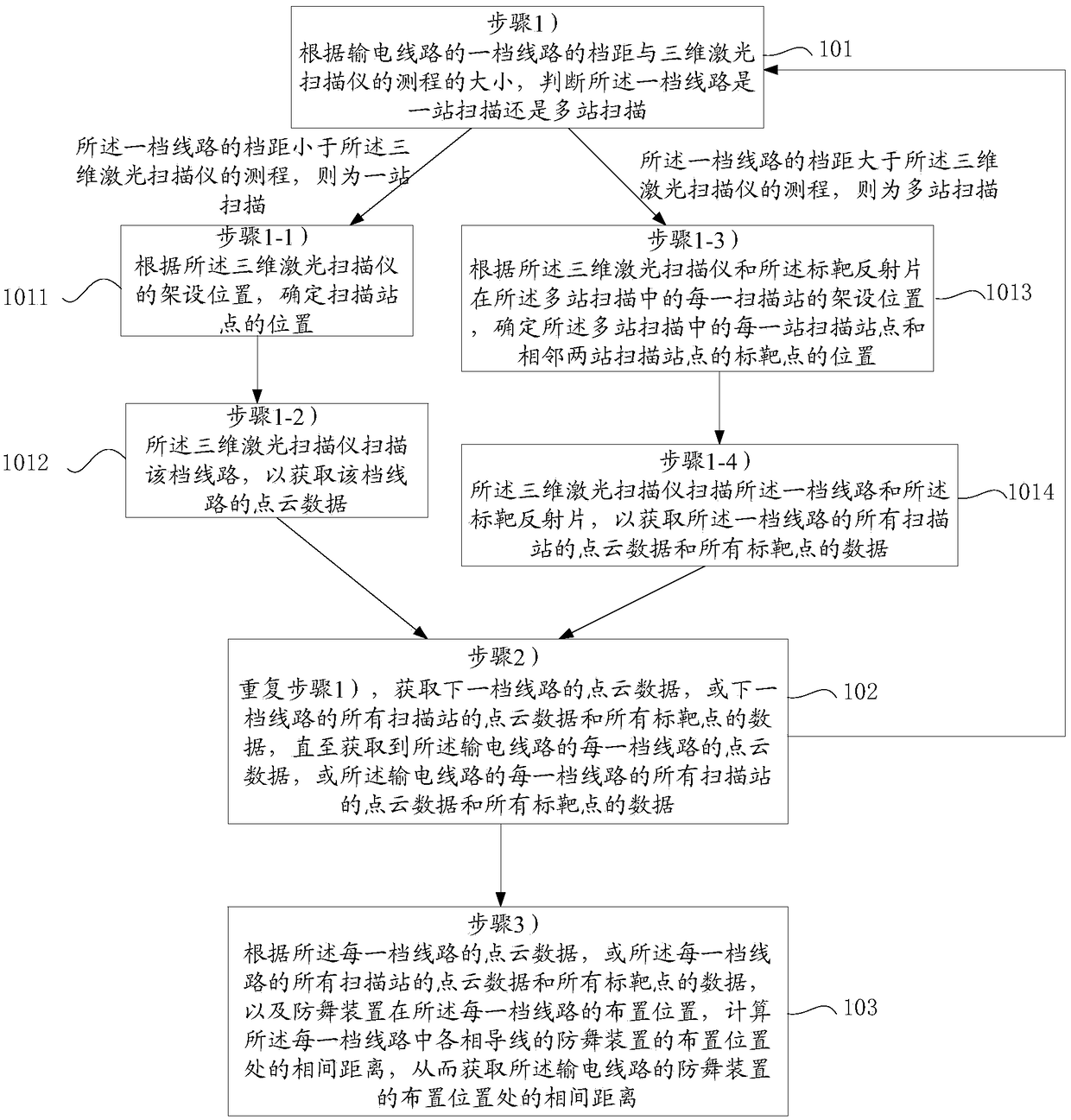
[0058] This embodiment provides a method for obtaining the phase-to-phase distance at the arrangement position of the anti-dancing device of the transmission line, see figure 1 , including the following steps:

[0059] 101: Step 1) According to the span of the first gear line of the power transmission line and the size of the measurement range of the three-dimensional laser scanner, it is judged whether the first gear line is scanned by one station or multi-station;

[0060] If the span of the first gear line is less than the measuring range of the three-dimensional laser scanner, then it is a one-station scan, and step 1-1) and step 1-2) are performed;

[0061] 1011: Step 1-1) Determine the location of the scanning site according to the installation location of the 3D laser scanner;

[0062] 1012: The 3D laser scanner in step 1-2) scans the line to obtain the point cloud data of the line;

[0063] If the span of the first gear line is greater than the range of the three-dim...

Embodiment 2

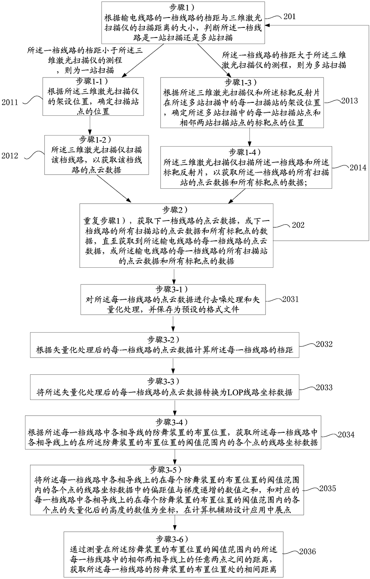
[0077] 201: Step 1) According to the span of the first gear line of the power transmission line and the size of the measurement range of the three-dimensional laser scanner, it is judged whether the first gear line is scanned by one station or multi-station;

[0078] If the span of the first gear line is less than the measuring range of the three-dimensional laser scanner, then it is a one-station scan, and step 1-1) and step 1-2) are performed;

[0079] 2011: step 1-1) determine the position of the scanning site according to the erection position of the 3D laser scanner;

[0080] 2012: The three-dimensional laser scanner in step 1-2) scans the file line to obtain the point cloud data of the file line;

[0081] If the span of the first gear line is greater than the range of the three-dimensional laser scanner, it is multi-station scanning, and steps 1-3) and steps 1-4) are performed;

[0082] 2013: Step 1-3) According to the erection position of each scanning station in the m...

Embodiment 3

[0103] Step 1) Field survey, select the scanning site and target point position according to the terrain conditions; according to the existing transmission line route, positioning records and other data, field survey, according to the terrain conditions in the target file and the 3D laser used The performance of the scanner, the selection of the appropriate scanning site and the position of the target point, the purpose is to obtain the point cloud data of the ideal scanning station and the information of the connection points of each scanning station. For example: a line with a gear distance of 800m can be divided into three stations to scan the line.

[0104] Step 2) Set up a ground laser scanning system (mainly a 3D laser scanner) and a scanning reflector at a location with good terrain conditions; set up a Riegl VZ1000 3D laser scanner at the selected scanning site, level the instrument, connect and Test whether the communication connection between the 3D laser scanner and...


PUM


Abstract

The invention discloses a method for acquiring interphase distances at layout positions of anti-galloping devices of a power transmission line. The method comprises the steps of: step 1) determining whether a span of line undergoes one-station scanning or multi-station scanning, executing step 1-1) and step 1-2) when the span of line undergoes one-station scanning, and executing step 1-3) and step 1-4) when the span of line undergoes multi-station scanning, wherein the step 1-1) is implemented by determining a position of a scanning station point, the step 1-2) is implemented by acquiring point cloud data of the span of line, the step 1-3) is implemented by determining positions of each scanning station point and target points of two adjacent scanning station points in multi-station scanning, and the step 1-4) is implemented by acquiring point cloud data of all scanning stations and data of all the target points of the span of line; step 2) repeating the step 1), and acquiring point cloud data of a next span of line, or point cloud data of all scanning stations and data of all target points of the next span of line; step 3) and calculating the interphase distances at the layout positions of the anti-galloping devices of phases of conductors in each span of line. The method has the advantages of acquiring a large amount of data, and having low requirements for wind force and terrain.

Description

technical field [0001] The invention relates to the technical field of power grid engineering, in particular to a method for obtaining the phase-to-phase distance at the arrangement position of an anti-dancing device of a power transmission line. Background technique [0002] Since 2009, under the influence of low temperature, rain and snow, there have been many transmission line gallops across the country, causing short-circuit tripping of transmission lines and damage to different mechanical components. To this end, the State Grid Corporation of China has formulated and issued the "Design Requirements for Dance Prevention of New Transmission Line Projects of State Grid Corporation of China", which requires that dance prevention measures be taken as soon as possible for the transmission line projects that have been built and are under construction in the area where galloping occurs. [0003] The main measure of anti-dancing treatment of the built transmission lines is to in...

Claims


Application Information

Patent Timeline
Patent Type & Authority Patents(China)
IPC IPC(8): G01B11/14
CPCG01B11/14
Inventor 高春林吉天翔史仲赵瑞乔金海刘超顾志强贾士军
Owner STATE NUCLEAR ELECTRIC POWER PLANNING DESIGN & RES INST CO LTD
Learn More