Bridge sign device

A technology for signs and bridges, applied in the direction of preventing contact with live contacts, roads, road signs, etc., can solve problems such as affecting the normal passage of vehicles on the bridge, easily exposed to the outside world, and unstable power supply methods. To achieve the effect of simple structure, avoiding the risk of electric shock, and stable power supply connection

Active Publication Date: 2017-08-22
江苏中路交通发展有限公司
View PDF7 Cites 1 Cited by
  • Summary
  • Abstract
  • Description
  • Claims
  • Application Information

AI Technical Summary

Problems solved by technology

However, the signage needs to be powered when it is working. In the prior art, the power supply is generally through the plug-in method. The power supply method is not stable. When the wind on the bridge is strong, the signboard is easily shaken due to the large force-bearing area. As a result, the plug port is loose and the power supply connection is interrupted, causing traffic disorder and seriously affecting the normal passage of vehicles on the bridge. At the same time, the traditional signage connection method makes the power port easily exposed to the outside world. Very prone to conduction phenomenon, there is a greater safety hazard

Method used


Image

  • Bridge sign device
  • Bridge sign device
  • Bridge sign device

Examples


Embodiment Construction

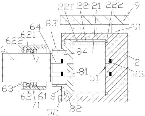
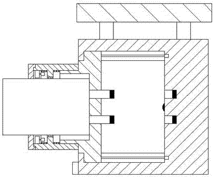
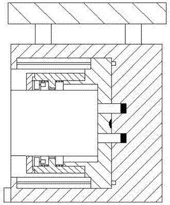
[0019] Such as Figure 1-Figure 4 As shown, a bridge indicator device of the present invention includes a base 2, and a push cavity 21 is arranged in the base 2, and sliding joint cavities 22 are respectively arranged on the upper and lower sides of the push cavity 21, and the sliding joint cavity 22 A screw rod 221 is provided, and the right side end of the screw rod 221 is power-connected with the first driving machine 222, and a sliding block 8 is arranged in the moving cavity 21, and the upper and lower sides of the sliding block 8 are respectively provided with entry points. The push block 82 in the sliding joint cavity 22, the push block 82 is helically connected with the screw rod 221, and the left side of the sliding joint block 8 is provided with an external helical joint 83, and the external helical joint 83 is provided with a placement groove 84, and the slide block 8 on the right side of the placement groove 84 is provided with a slide hole 81, and the correspondin...


PUM


Abstract

The invention discloses a bridge sign device which comprises a pedestal, wherein a pushing cavity is arranged in the pedestal; sliding cavities are correspondingly arranged at the upper and lower sides of the pushing cavity; each sliding cavity is provided with a screw rod, and the right side end of each screw rod is in power connection with a first driving machine; a sliding block is arranged in the pushing cavity; pushing blocks capable of entering the sliding cavities are correspondingly arranged at the upper and lower sides of the sliding block; the pushing blocks are connected with the screw rods by threaded fit; an external thread joint part is arranged at the left side of the sliding block; a containing groove is formed in the external thread joint part; sliding holes are formed in the part, at the right side of the containing groove, of the sliding block; pin holes are formed in the corresponding parts, at the right sides of the sliding holes, on the inner wall of the pedestal; and a sign is correspondingly arranged at the left side of the containing groove. The bridge sign device disclosed by the invention is simple in structure, convenient to operate, high in safety and relatively stable in power supply connection, and effectively avoids the electric shock hazard when a person touches the pin holes.

Description

technical field [0001] The invention relates to the technical field of signboards used on bridges, in particular to a bridge signboard device. Background technique [0002] Various signboards can often be seen on some bridges, which are mainly used for traffic guidance to passing vehicles or to remind or warn vehicles passing on the bridge under bad weather conditions. However, the signage needs to be powered when it is working. In the prior art, the power supply is generally through the plug-in method. The power supply method is not stable. When the wind on the bridge is strong, the signboard is easily shaken due to the large force-bearing area. As a result, the plug port is loose and the power supply connection is interrupted, causing traffic disorder and seriously affecting the normal passage of vehicles on the bridge. At the same time, the traditional signage connection method makes the power port easily exposed to the outside world. It is very prone to conduction pheno...

Claims


Application Information

Patent Timeline
Patent Type & Authority Applications(China)
IPC IPC(8): E01F9/608E01F9/615E01F9/623E01F9/40H01R13/44
CPCH01R13/44
Inventor 黄龙飞
Owner 江苏中路交通发展有限公司
Why Eureka
Try Eureka