
DC vibration motor

A technology of vibrating motors and casings, which is applied in the direction of electrical components, electromechanical devices, and electric components. It can solve the problems of small output torque, small winding space, and complicated winding, and achieve the effect of large output torque and convenient assembly.

Active Publication Date: 2017-08-18
东莞市维斗科技股份有限公司
View PDF3 Cites 1 Cited by
  • Summary
  • Abstract
  • Description
  • Claims
  • Application Information

AI Technical Summary

Problems solved by technology

However, the motor with the second structure uses a single wire package, the winding space is small, and the winding is complicated, the efficiency is low, the flatness is poor, the output torque is small, and the assembly process is complicated.

Method used


Image

  • DC vibration motor
  • DC vibration motor
  • DC vibration motor

Examples


Embodiment Construction

[0024] The technical solutions in the embodiments of the present invention are clearly and completely described below in conjunction with the accompanying drawings in the embodiments of the present invention. Obviously, the described embodiments are only part of the embodiments of the present invention, not all of them. Based on the embodiments of the present invention, all other embodiments obtained by persons of ordinary skill in the art without making creative efforts belong to the protection scope of the present invention.

[0025] In the following description, a lot of specific details are set forth in order to fully understand the present invention, but the present invention can also be implemented in other ways different from those described here, and those skilled in the art can do it without departing from the meaning of the present invention. By analogy, the present invention is therefore not limited to the specific examples disclosed below.

[0026] like Figure 3-...


PUM


Abstract

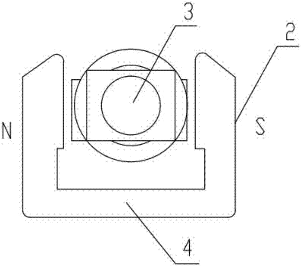
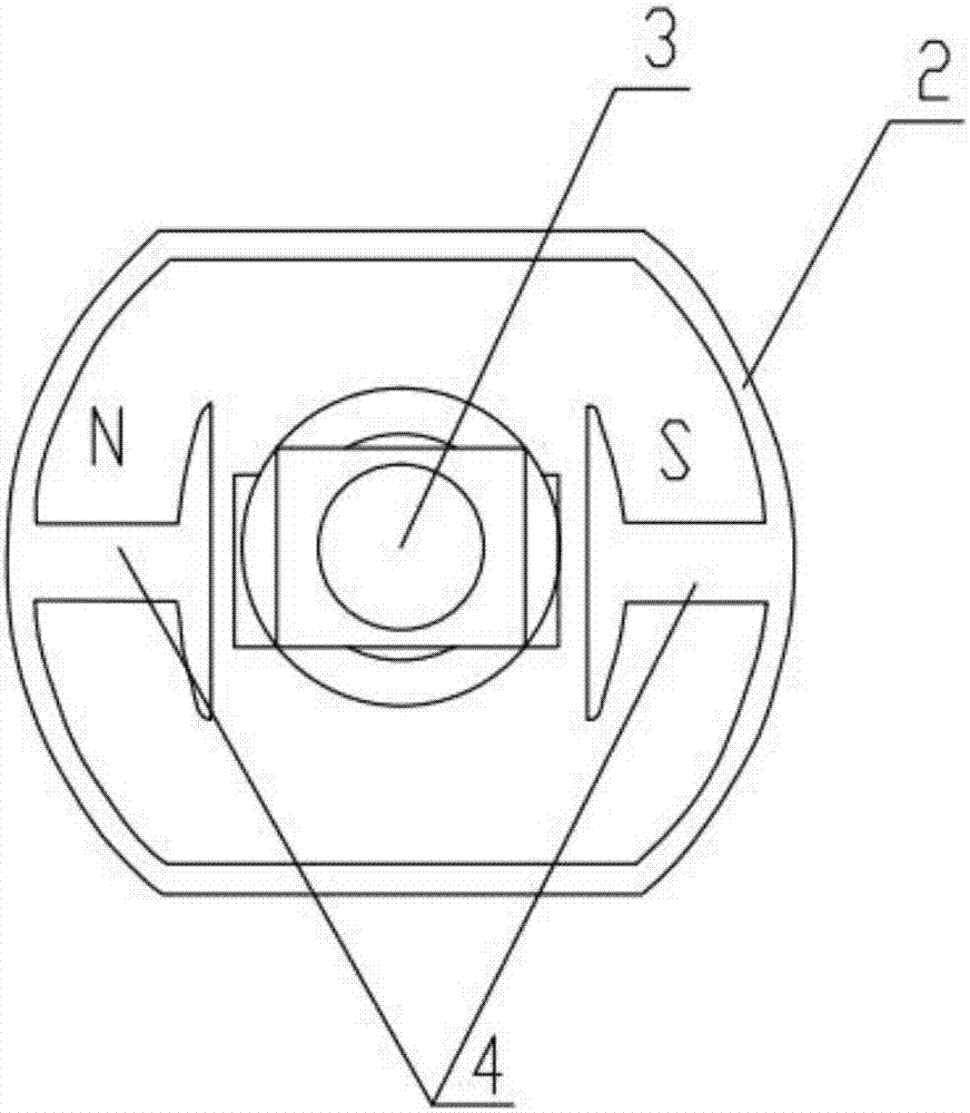
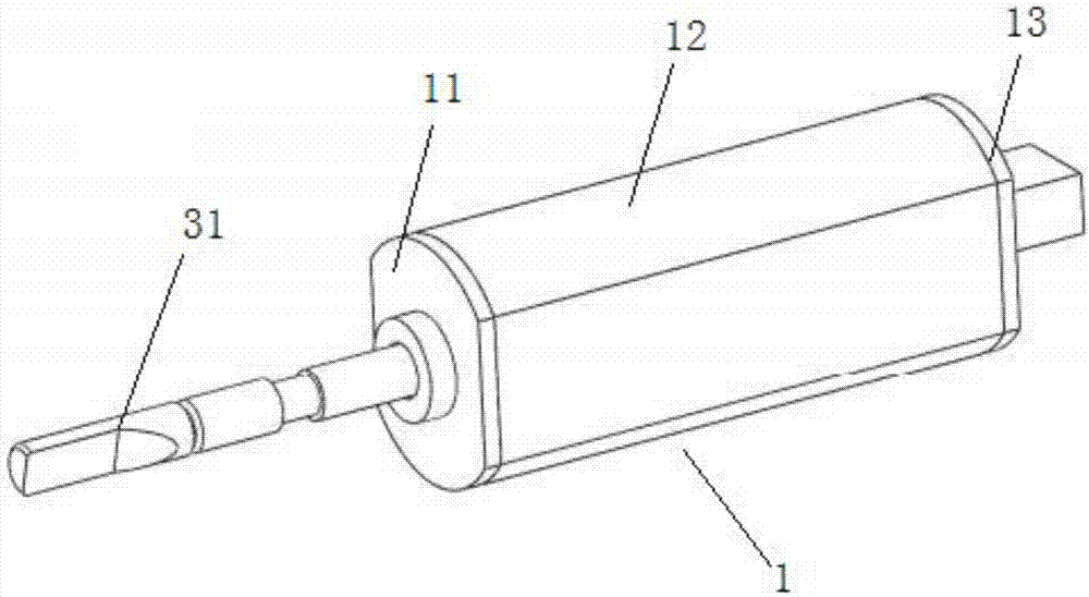
The invention discloses a DC vibration motor, relating to a technical field of the motor having one rotor and one stator. The motor comprises a housing, a stator and a rotor; the stator comprises an upper winding shaft, a lower winding shaft, a stator group and coils; a stator group comprises a C-shaped left stator group and a C-shaped right stator group; two free ends of the left stator group and the right stator group are arranged oppositely and then a rectangle-shaped coil winding frame is constituted; the coils are respectively wound on two horizontal parts of the winding frame; and after two coils are simultaneously powered on, the N poles and the S poles of the two coils are on same sides, and the S poles and the N poles of the two coils are on other same sides. The left stator group and the right stator group which have single polarity interact with each other to form an external magnetic field; a magnetic field torque is generated between the external magnetic field and the rotor to drive the rotor to rotate; and strength of a magnetic field under a common action of two winding coils are bigger, so that the output torque of the motor is bigger.

Description

technical field [0001] The invention relates to the technical field of a motor with a rotor and a stator, in particular to a DC vibration motor with a larger output torque. Background technique [0002] Devices such as electric toothbrushes, cell phones, portable game consoles, or pagers use vibration motors. There are roughly two types of vibrating motors in the prior art, one with a structure such as figure 1 As shown, the shaft is set eccentrically, and this structure cannot achieve the shaft at the center (under the same requirements, the force and space are not enough). Another structure such as figure 2 As shown, the axis is set in the center. However, the motor with the second structure uses a single wire package, the winding space is small, the winding is complicated, the efficiency is low, the flatness is poor, the output torque is small, and the assembly process is complicated. Contents of the invention [0003] The technical problem to be solved by the pres...

Claims


Application Information

Patent Timeline
Patent Type & Authority Applications(China)
IPC IPC(8): H02K7/06
CPCH02K7/06
Inventor 钟木生
Owner 东莞市维斗科技股份有限公司
Learn More