
Virtual synchronous generator self-synchronizing control method based on phase difference real-time regulation

A technology of synchronous generators and virtual synchronization, applied to electrical components, circuit devices, AC network circuits, etc., can solve problems such as increased costs, difficulties in phase measurement, and reduced information accuracy

Active Publication Date: 2017-08-18
NORTH CHINA ELECTRIC POWER UNIV (BAODING)
View PDF3 Cites 8 Cited by
  • Summary
  • Abstract
  • Description
  • Claims
  • Application Information

AI Technical Summary

Problems solved by technology

Although there have been discussions on the switching strategy under the VSG control mode, most of the existing strategies for inverter grid connection require a "pre-synchronization" process. The default condition is that the phase of the grid side is known and can be measured
However, in practical applications, there are situations where phase measurement is difficult
Even if the phase information of the power grid can be easily measured, the information must be transmitted from the grid side to the controller, which will increase the delay time, reduce the accuracy of the information, and increase the cost

Method used


Image

  • Virtual synchronous generator self-synchronizing control method based on phase difference real-time regulation
  • Virtual synchronous generator self-synchronizing control method based on phase difference real-time regulation
  • Virtual synchronous generator self-synchronizing control method based on phase difference real-time regulation

Examples


Embodiment Construction

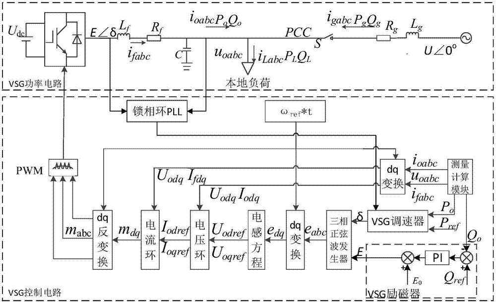
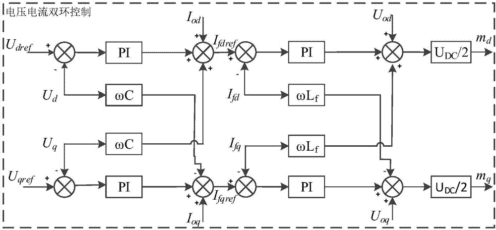
[0025] The self-synchronization control method of the virtual synchronous generator based on the phase difference real-time adjustment will be described in detail below with reference to the accompanying drawings and examples. It should be emphasized that the following description is only exemplary and not intended to limit the scope of the invention and its application.

[0026] Example: The VSG runs with a local load of about 60kW, and runs with a local load island in 0-3s; it is connected to the grid at 3s and off-grid at 6s. The phase angle difference between the inverter output voltage (filter capacitor voltage) and the PCC voltage before grid connection is 0.08rad.

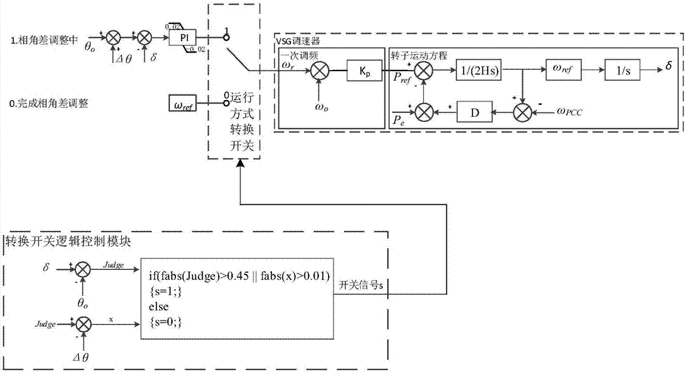
[0027] Step 1: Calculate the voltage phase difference Δθ on both sides of the filter inductor corresponding to the output power of the inverter power supply. For a pair of pole saliency machines, when the inductance is much greater than the resistance, the quadrature-axis synchronous reactance is equal to t...


PUM


Abstract

The present invention provides a virtual synchronous generator self-synchronizing control method based on phase difference real-time regulation, belonging to the new energy electric power conversion technology field. The technical steps comprises: calculating voltage phase difference [Delta][Theta] of two sides of a filtering inductor in a corresponding inverter output power; employing a phase-locked loop (PLL) to collect voltage phase information of two sides of the LC filter inductor; calculating phase angle determination signals Judge=[Delta]-[Theta]o; calculating regulation determination signals x=Judge-[Delta][Theta]; editing a conversion switch logic control module; and constructing an operation mode conversion switch logic. The virtual synchronous generator self-synchronizing control method based on the phase difference real-time regulation calculates phase angle difference corresponding to a target power value in real time, rapidly regulates voltage phase angle difference of two sides of the LC filter inductor and realizes self synchronization with the power grid with no need for power grid phase information and the presynchronization link. The virtual synchronous generator self-synchronizing control method based on the phase difference real-time regulation enhances control of the power grid side to a distributed generation to allow the distributed generation to be better serve the power grid. The virtual synchronization generator employs an uniform inner ring control structure when the virtual synchronization generator performs island / grid-connected operation so as to avoid causing stability problem caused by changing of inner ring control.

Description

technical field [0001] The invention belongs to the technical field of new energy power conversion, and in particular relates to a self-synchronization control method of a virtual synchronous generator based on phase difference real-time adjustment. Background technique [0002] The types and proportions of new energy in the power grid are gradually increasing. Distributed wind power and photovoltaics are often connected to the grid in the form of micro-grids through inverters. Whether they can smoothly switch between grid-connected and off-grid states has become one of the important goals of inverter control. . Due to the lack of inertia of the power system caused by the increase in the number of inverters in recent years, the concept of virtual synchronous generator (VSG) has gradually received attention, and the algorithm for simulating the operating characteristics of synchronous generators has been introduced into the control strategy of the inverter. Make the inverter...

Claims


Application Information

Patent Timeline
Patent Type & Authority Applications(China)
IPC IPC(8): H02J3/40H02J3/38
CPCH02J3/381H02J3/40
Inventor 袁敞赵天扬郝毅丁雨霏谢佩琳肖湘宁
Owner NORTH CHINA ELECTRIC POWER UNIV (BAODING)
Learn More