Compact explosion-proof protector

A protector, compact technology, applied in the direction of emergency protection devices, electrical components, circuits, etc., can solve the problems of the limitation of explosion-proof performance, the difficulty of realizing arc extinguishing materials, and the inability to reduce the volume, so as to achieve space saving, good flexibility and High adsorption and strong long-term stability

Inactive Publication Date: 2017-08-18
NANJING SART SCI & TECH DEV
View PDF9 Cites 2 Cited by
  • Summary
  • Abstract
  • Description
  • Claims
  • Application Information

AI Technical Summary

Problems solved by technology

[0002] The current overcurrent protectors mainly include pin type and patch type. The pin type structure is shown in Chinese patent 201420307171.4, which is composed of base, cover, lead wire, melt and lead wire fixing terminal. Its breaking capacity is relatively high. High, anti-knock performance is good, but the size cannot be reduced, and the rapid development of electronic products has higher and higher requirements for components mounted on the circuit board, the overcurrent protector must achieve compact size, and change from the pin type to the surface SMT type, in order to meet the requirements of miniaturization
Another patch type, as shown in Chinese patent 201320556184.0, consists of an insulating substrate, front and back electrodes, fusing metal layer, protective layer, internal electrodes and terminal electrodes. Its volume can be made very small, but this structure The smaller the size of the protector, the smaller the I2t that the protector can achieve, and due to the limited space, the improvement of the explosion-proof performance is also limited and cannot be improved
In addition, for the products of the above two structures, in order to improve the anti-knock ability of the product, an arc-extinguishing material is arranged around the melt, and a cavity is formed around the melt, and the arc-extinguishing material is filled in the cavity. The volume requirements are getting smaller and smaller, and it is becoming more and more difficult to fill the cavity with arc-extinguishing materials

Method used


Image

  • Compact explosion-proof protector
  • Compact explosion-proof protector
  • Compact explosion-proof protector

Examples


Embodiment 1

[0028] The composition of the arc extinguishing material is as follows by weight: 10 parts of polyamide resin or polyimide resin or silicone resin, 6 parts of anhydrous magnesium oxide, 5 parts of gas phase silicon dioxide, and 0.2 part of sodium chloride.

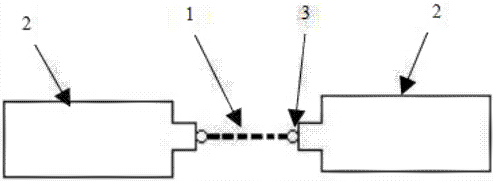
[0029] Such as figure 1 As shown, a whole melt with arc-extinguishing material attached is cut into a small section, and the tinned copper sheet is processed into a "convex" shape as electrode 2. The width of the joint between electrode 2 and melt 1 is narrow, and electrode 2 and The melt 1 is welded together by solder beads 3 to form an electrical connection, the electrode 2 coincides with the center line of the melt 1, and both are placed horizontally.

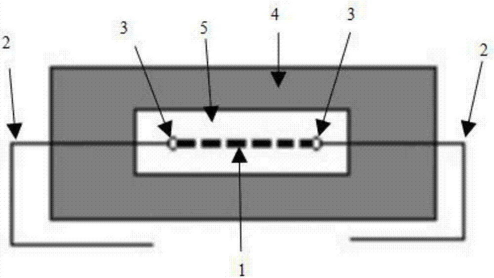
[0030] Such as figure 2 As shown, an encapsulation layer 4 is formed outside the melt 1 by plastic sealing, a cavity is formed in the encapsulation layer 4, the melt 1 is suspended in the cavity, and there is a certain gap between the arc extinguishing material 7 and t...

Embodiment 2

[0033] The composition of the arc extinguishing material is as follows by weight: 10 parts of polyamide resin or polyimide resin or silicone resin, 6 parts of anhydrous magnesium oxide, 5 parts of gas phase silicon dioxide, and 0.2 part of sodium chloride.

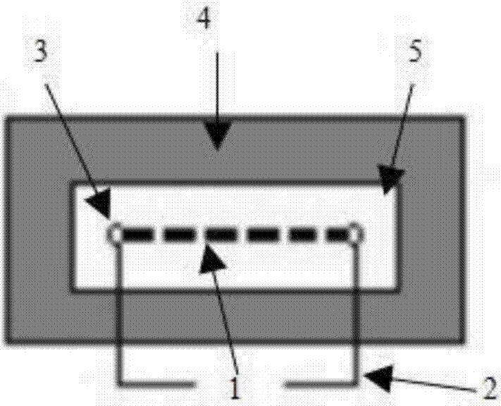
[0034] Such as image 3 As shown, the electrode 2 is processed into a "convex" shape, and is welded together with the melt 1 by solder beads 3 to form an electrical connection. Dip into the mixed arc extinguishing material, then bake and solidify. The electrode 2 is perpendicular to the center line of the melt 1, and the melt 1 is placed horizontally. A part of the electrode 2 protrudes out of the encapsulation layer and is bent into a relative right angle after processing. The bottom part is horizontal and close to the encapsulation layer. There is no contact between the two "L" shaped right angles.

[0035] The advantage of this embodiment is that the electrode 2 is perpendicular to the melt 1, and after the melt is as...

Embodiment 3

[0037] The composition of the arc extinguishing material is as follows by weight: 10 parts of polyamide resin or polyimide resin or silicone resin, 6 parts of anhydrous magnesium oxide, 5 parts of gas phase silicon dioxide, and 0.2 part of sodium chloride.

[0038] Such as Figure 4As shown, the electrode 2 and the melt 1 are welded together by solder beads 3 to form an electrical connection, and then part of the melt is dipped into the arc extinguishing material, and baked and solidified. The electrode 2 is perpendicular to the center line of the melt 1, and the melt 1 placed horizontally. The encapsulation layer 4 wraps the melt 1, the arc extinguishing material 7, the fixed terminals 3 on both sides, and a part of the electrodes 2 on both sides. The substrate 6 is arranged under the encapsulation layer 4, and the electrodes 2 extend into the substrate 6 through the encapsulation layer 4. , and bend to both sides to protrude from the substrate, and the part protruding from ...


PUM


Abstract

The present invention provides a compact explosion-proof protector. The compact explosion-proof protector comprises a melt, electrodes, an encapsulation layer and an arc extinguishing material; two electrodes are provided; the melt is arranged between the two electrodes; the arc extinguishing material is attached onto the melt; the encapsulation layer forms a cavity; the melt is located in the cavity; and the electrodes pass through the encapsulation layer. The arc extinguishing material is made of the following components in parts by weight: 10 to 12 parts of polyamide resin or polyimide resin or silica gel resin; 4 to 8 parts of anhydrous magnesium hydroxide; 3 to 7 parts of fumed silica; and 0.1 to 0.5 part of sodium chloride. The compact explosion-proof protector of the invention has the advantages of decreased size and improved explosion-proof performance.

Description

technical field [0001] The invention relates to a protector technology, in particular to a compact explosion-proof protector. Background technique [0002] The current overcurrent protectors mainly include pin type and patch type. The pin type structure is shown in Chinese patent 201420307171.4, which is composed of base, cover, lead wire, melt and lead wire fixing terminal. Its breaking capacity is relatively high. High, anti-knock performance is good, but the size cannot be reduced, and the rapid development of electronic products has higher and higher requirements for components assembled on the circuit board, the overcurrent protector must achieve compact size, and change from the pin type to the surface Mounting type, in order to meet the requirements of miniaturization. Another patch type, as shown in Chinese patent 201320556184.0, consists of an insulating substrate, front and back electrodes, fusing metal layer, protective layer, internal electrodes and terminal ele...

Claims


Application Information

Patent Timeline
IPC IPC(8): H01H85/02H01H85/147H01H85/38
CPCH01H85/0241H01H85/147H01H85/38H01H2085/0275H01H2085/388
Inventor 南式荣唐彬艾莹露
Owner NANJING SART SCI & TECH DEV
Why Eureka
Try Eureka