
Road construction area speed reduction and speed measurement-integrated safety control and information feedback system

A technology for road construction and safety control, applied in the traffic control system of road vehicles, traffic control system, roads, etc., can solve the problem that construction warning signs do not conform to standard specifications, vehicle speed limit warning effect is not good, and speed limit signs do not follow each other. In order to achieve the effect of significant promotion value and economic benefits, excellent safety performance, fast and easy installation and movement

Inactive Publication Date: 2017-08-18
CHANGAN UNIV
View PDF6 Cites 4 Cited by
  • Summary
  • Abstract
  • Description
  • Claims
  • Application Information

AI Technical Summary

Problems solved by technology

[0003] Although there are passive reminder signs and cone-shaped traffic signs in the road construction area at present, these signs are not set accurately, the setting interval is too large, the required installation time is long, the speed limit signs do not descend step by step, and the construction warning signs do not meet the standard specifications etc., which makes the warning effect unsatisfactory; and the road section in the construction area uses the method of speed limit signs to limit the speed passively, the function is single and limited, the speed limit warning effect on vehicles is not good, and there is a lack of active speed limit technology and active feedback to drivers. (such as whether the vehicle exceeds the speed limit), the driver will often cause safety hazards due to negligence; due to the randomness and short-term characteristics of daily maintenance, and the lack of feedback on the current traffic information of the construction area, it is difficult to let The driver knows the specific situation of the construction road section in advance

Method used

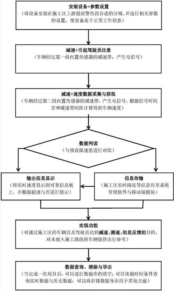
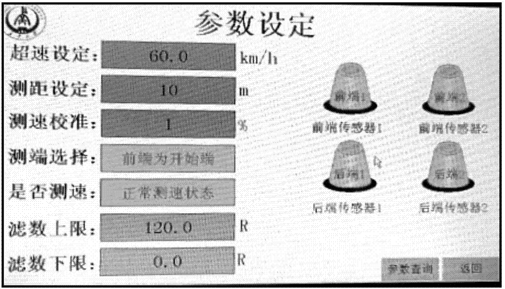

Image

  • Road construction area speed reduction and speed measurement-integrated safety control and information feedback system
  • Road construction area speed reduction and speed measurement-integrated safety control and information feedback system
  • Road construction area speed reduction and speed measurement-integrated safety control and information feedback system

Examples


Embodiment Construction

[0023] In order to better understand the technical content of the present invention, specific embodiments are given and described as follows in conjunction with the accompanying drawings.

[0024] The integrated safety control and information feedback system of deceleration and speed measurement in the road construction area is mainly installed in the early warning section of the road construction area.

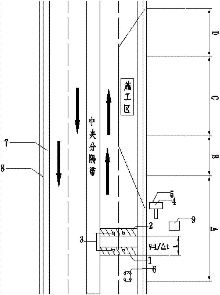
[0025] Such as figure 1 As shown, the system includes: the first group of portable speed bumps 1, the second group of portable speed bumps 2, and two sets of grooved speed bumps, which are arranged at intervals along the driving direction on the corresponding lanes in front of the construction area. The two sets of grooved speed bumps The speed bump adopts a groove-shaped hollow body made of rubber, and two 801s vibration sensors 3 are installed in each groove, which can collect electric signals generated by vehicle vibration while reducing the speed of the vehicle; the porta...


PUM


Abstract

The invention provides a road construction area speed reduction and speed measurement-integrated safety control and information feedback system, which comprises two groups of groove-type speed reduction belts; each groove is internally provided with two vibration sensors; a portable variable information board is used for displaying a limited speed, a real-time vehicle speed and the real-time road condition information in the construction area; and an information processing unit is used for converting electric signals to vehicle speed information and processing stored data. An active information feedback technology is used to replace the original passive sign, the driver can know the vehicle speed and the road condition information better, an effective reminding role is played, the safety accidents can be reduced greatly, the system cost is low, the technology is simple, and realization is easy.

Description

technical field [0001] The invention belongs to the technical field of traffic safety in road construction areas, and in particular relates to an integrated safety control and information feedback system for deceleration and speed measurement in road construction areas. Background technique [0002] With the vigorous development of my country's economic construction, the number of road projects is increasing day by day. In the first half of 2016, 4,500 kilometers of highways were added, 16,000 kilometers of national and provincial arterial roads were newly rebuilt, and 180,000 kilometers of rural roads were rebuilt. With the increase in the number of reconstruction, expansion and maintenance projects, the traffic conditions in the construction area are becoming more and more complicated, and the resulting problems have attracted more and more people's attention. The road construction area is a special traffic management area set up for road maintenance and repair operations....

Claims


Application Information

Patent Timeline
IPC IPC(8): G08G1/052E01F9/529E01F11/00
CPCG08G1/052E01F11/00
Inventor 张驰张宏张敏崔星和磊王博刘园园祝文君
Owner CHANGAN UNIV
Learn More