Multichannel V-groove type optical coupling inserting core

An optical coupling, multi-channel technology, applied in the coupling of optical waveguides, light guides, optics, etc., can solve the problems of labor-hour cost and grinding consumables cost, surface material damage of guide pinholes, high cost, etc., to promote high density and low energy. Consumption, optimized structure, easy to repeat the effect of plugging and unplugging

Pending Publication Date: 2017-08-18
苏州天孚永联通信科技有限公司
View PDF7 Cites 0 Cited by
  • Summary
  • Abstract
  • Description
  • Claims
  • Application Information

AI Technical Summary

Problems solved by technology

Consumes a lot of man-hour cost and grinding consumable cost
[0003] The injection molding of the ferrule adopts the method of high-precision pin insertion and injection molding, which requires high precision and position of the pin itself. To realize the application of single-mode optical fiber with low loss, it will bring the cost of mold development and injection molding very expensive
In addition, the guide pin hole of this type of ferrule is also adopted without chamfering through the hole. This structure will cause the surface material of the guide pin hole to be damaged when the subsequent metal guide pin is repeatedly inserted and pulled into the guide pin hole.
[0004] To sum up, the existing MT-type ferrule is a multi-channel fiber optic connector ferrule based on conventional docking, and its assembly process highlights the shortcomings of complex process and high cost in the field of optical coupling.
In addition, in order to achieve the low-loss coupling alignment accuracy requirements of single-mode fiber, its mold development and injection molding costs are very high

Method used


Image

  • Multichannel V-groove type optical coupling inserting core
  • Multichannel V-groove type optical coupling inserting core

Examples


Embodiment Construction

[0021] The present invention will be further described below in conjunction with the accompanying drawings and embodiments.

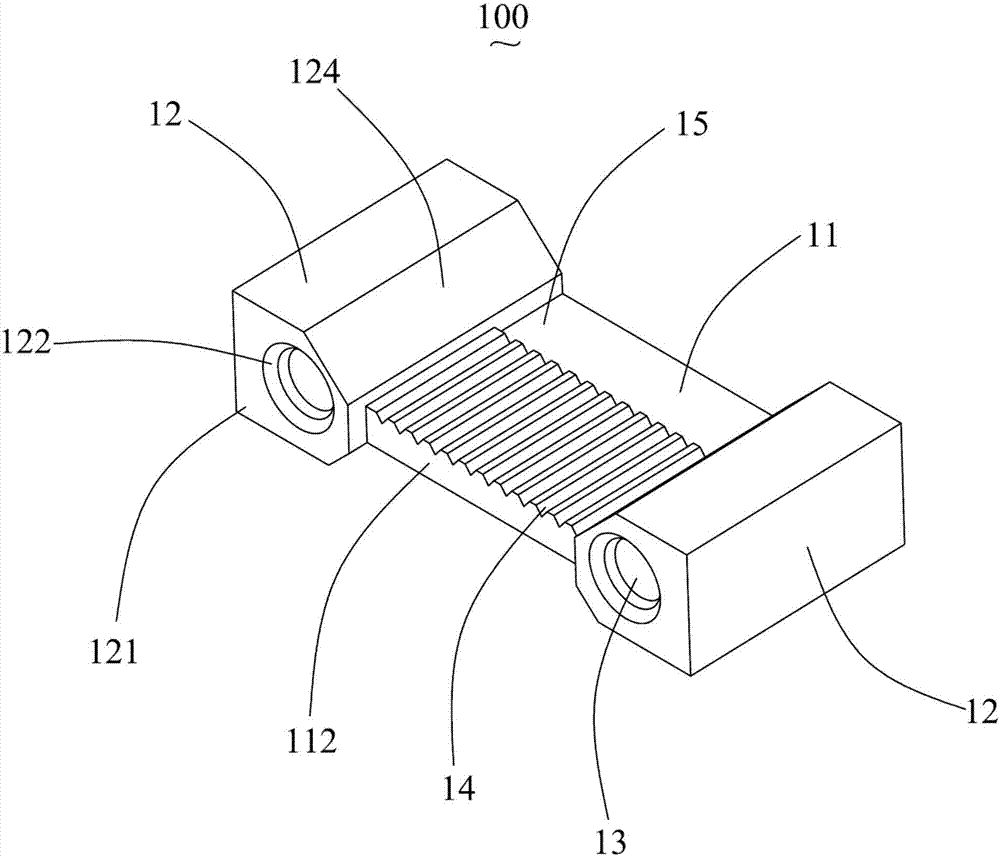
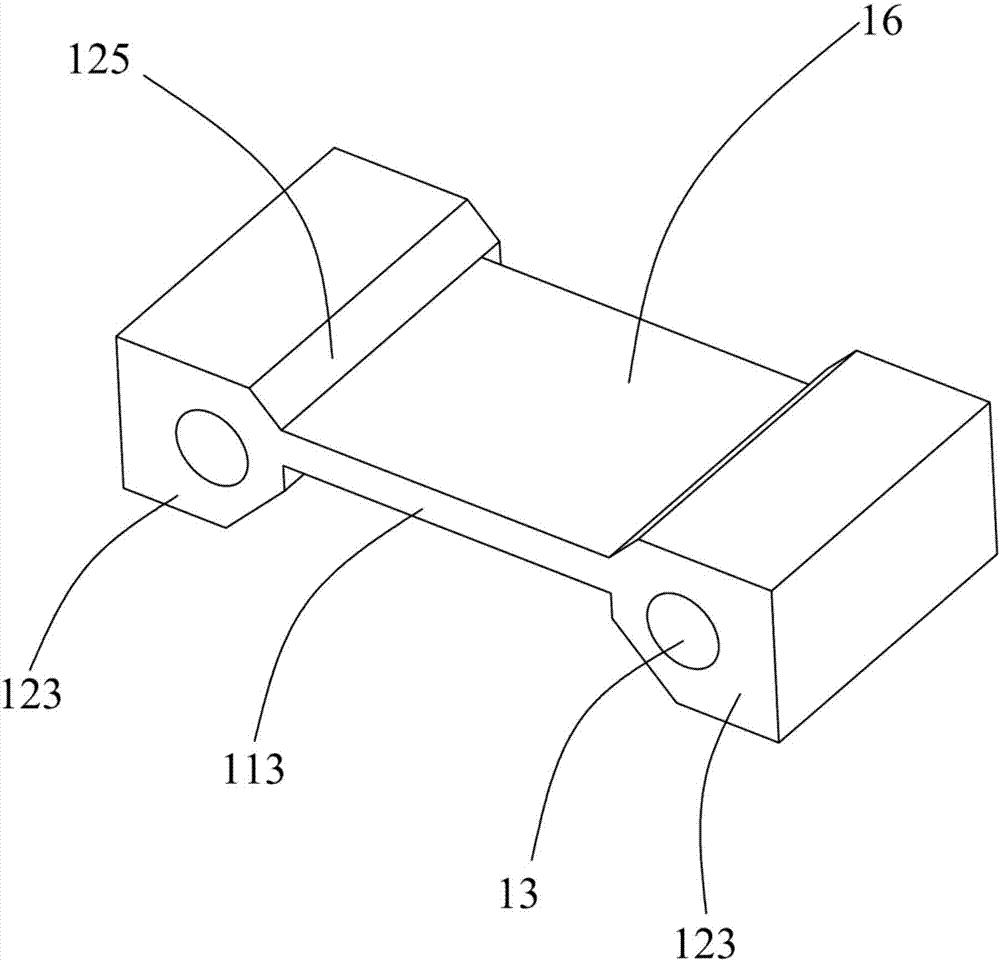
[0022] like Figure 1 to Figure 2 As shown, it is a multi-channel V-groove optical coupling ferrule 100 according to the present invention, which includes: an optical fiber hole plate 11 and two guide pin hole barrels 12 located on both lateral sides of the fiber hole plate 11, the guide pins The hole barrel 12 is provided with a guide pin hole 13 penetrating along the front and back direction, and the optical fiber hole plate 11 is provided with a row of fiber positioning holes 14 . The optical fiber hole plate 11 is recessed backwards relative to the two guide needle hole cylinders 12, so as to reserve a working distance for laser cutting.

[0023] The guide pin hole barrel 12 is provided with a front end surface 121 and a chamfered structure 122 located on the front end surface 121 of the guide pin hole barrel 12 . The thickness of the optical fibe...


PUM


Abstract

The invention discloses a multichannel V-groove type optical coupling inserting core. The multichannel V-groove type optical coupling inserting core comprises an optical fiber hole plate and two guide pin hole cylinders locating on two transverse sides of the optical fiber hole plate, each guide pin hole cylinder is provided with a guide pin hole penetrating in the front and back direction, and the optical fiber hole plate is provided with a row of optical fiber positioning holes. The optical fiber hole plate is recessed backwards relative to the two guide pin hole cylinders, and then a working distance of laser cutting machining is reserved.

Description

technical field [0001] The invention relates to an optical coupling ferrule, in particular to a multi-channel V-groove optical coupling ferrule. Background technique [0002] The existing multi-channel fiber optic ferrule (Mechanical Transfer, MT-type ferrule for short) is all made of PPS material for injection molding. In practical applications, the front of the ferrule is processed by grinding, which needs to include: coarse grinding, fine grinding , Fine grinding, convex fiber grinding, polishing and grinding processes, including processing methods. It consumes a lot of man-hour cost and grinding consumable cost. [0003] The injection molding of the ferrule adopts the method of high-precision pin insertion and injection molding, which requires high precision and position of the pin itself. To realize the application of single-mode optical fiber with low loss, it will bring the cost of mold development and injection molding Very expensive. In addition, the guide pin ho...

Claims


Application Information

Patent Timeline
IPC IPC(8): G02B6/38
CPCG02B6/3839G02B6/3882G02B6/3885
Inventor 王志弘
Owner 苏州天孚永联通信科技有限公司
Why Eureka
Try Eureka