
Method and system for wireless ranging and vehicle collision avoidance warning

A wireless ranging and vehicle technology, applied in radio wave measurement system, radio wave reflection/re-radiation, measurement devices, etc., can solve the problems of frequency band hardware implementation and cost difficulty, non-single operating frequency, wide system frequency band occupation, etc. , to achieve the effects of reducing traffic accidents, saving frequency band resources, and saving hardware costs

Active Publication Date: 2020-04-28
袁学明
View PDF10 Cites 0 Cited by
  • Summary
  • Abstract
  • Description
  • Claims
  • Application Information

AI Technical Summary

Problems solved by technology

[0003] Directional radar reflected wave distance measurement: Since the signal is blocked by the nearest vehicle or building, only the operating conditions of the adjacent and nearest vehicles can be known, and the traffic conditions a little further away cannot be known in advance, such as the serial rear-end collision accident on the expressway
[0004] Inquiry-response: According to the literature, the most prominent disadvantages of this one-to-one response with multiplier feedback are: 1. It takes up a lot of time and is a waste of time. 3. The query-response ranging method is affected by the huge wave velocity of electromagnetic waves and the delay of the system, resulting in relatively large ranging errors. Big
[0005] One-way ranging (see application number 201210296473.1): This method also has serious shortcomings: 1. According to the literature, the transmission time is obtained from the frequency, and there are different frequencies at different times, so it occupies a large frequency band that is scarce itself, which is very wasteful Frequency band; 2. Due to the difference in system running time, it is difficult for the signal receiving terminal and the signal transmitting terminal to ensure accurate time synchronization, and the distance measurement method is affected by the huge wave velocity of electromagnetic waves, resulting in large measurement errors; 3. The wide frequency band is not suitable for hardware The implementation and cost of the

Method used


Image

  • Method and system for wireless ranging and vehicle collision avoidance warning
  • Method and system for wireless ranging and vehicle collision avoidance warning
  • Method and system for wireless ranging and vehicle collision avoidance warning

Examples


specific Embodiment 1

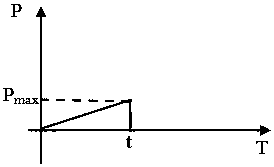
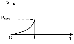
[0047] A wireless ranging method, the transmitter uses the maximum transmission power P max The electromagnetic wave signal is transmitted, and the receiving end receives the electromagnetic wave signal at the transmitting end, and records the time period ∆t during which the received signal strength is greater than or equal to the set threshold value ∆P within a signal period, or the period during which the received signal strength is greater than or equal to ∆P, The counter is counted to obtain the count value, and the distance between the receiving end and the transmitting end is determined according to the time length ∆t or the counter value; the electromagnetic wave signal emitted by the transmitting end adopts variable power, which satisfies the transmission power and time relationship function within a signal cycle monotonicity (such as Figure 1 to Figure 6 shown); the electromagnetic wave signal emitted by the transmitting end adopts a single frequency radiation.

specific Embodiment 2

[0049] On the basis of the specific embodiment 1, the electromagnetic wave signal emitted by the transmitting end adopts broadcast radiation. In this specific embodiment, the signal is transmitted in the form of broadcast for receiving by the receiving vehicle.

specific Embodiment 3

[0051] On the basis of the specific embodiment 1 or 2, the transmission power of the electromagnetic wave signal emitted by the transmitting end and the time relationship function are monotonously increasing or monotonically decreasing. Set a signal period as t, in the case of monotonically increasing (such as figure 1 , image 3 and Figure 5 shown), from time 0 to time t, the signal transmission power gradually increases, and reaches the maximum value P at time t max , and then drop to 0 instantly; in the case of monotonically decreasing (such as figure 2 , Figure 4 and Figure 6 Shown), the moment 0 moment reaches the maximum value, and then, from 0 moment to t moment, the signal transmission power gradually decreases, and reaches the minimum value at t moment. The minimum value may be 0, or a value whose signal strength is less than or equal to ΔP.


PUM


Abstract

The present invention provides a wireless ranging and vehicle anti-collision early-warning method and a system. A transmitting terminal transmits an electromagnetic wave at a maximum transmit power. A receiving terminal receives an electromagnetic wave signal sent by the transmitting terminal, calculates the time duration delta t for the signal strength received within one signal period to be larger than or equal to a threshold critical value delta P or the value of a counter, and determines the distance between the receiving terminal and the transmitting terminal according to the time duration delta t or the value of the counter. When the electromagnetic wave signal transmitted by the transmitting terminal meets the monotonicity property of the a transmitting power function within one signal period, the electromagnetic wave signal is radiated at a single frequency. A vehicle with the above receiving terminal is adopted as an original point, and more than two positions of a vehicle with the above transmitting terminal are measured based on the three-point positioning principle. If a straight line between two positions of the vehicle with the above transmitting terminal passes through the safety running range of the vehicle with the above receiving terminal, the distance is gradually reduced. Meanwhile, drivers are notified of conducting the early-warning operation in advance. The hardware circuit of the system is easy to realize, and low in hardware cost. Meanwhile, the problem of time synchronization between the transmitting terminal and the receiving terminal, and the influence of electromagnetic wave speeds are not considered. The measurement error is very small.

Description

technical field [0001] The invention relates to a method and system for wireless distance measurement and vehicle collision avoidance warning, in particular to a method and system for wireless distance measurement and vehicle collision avoidance warning applicable to the field of vehicle wireless distance measurement and collision avoidance. Background technique [0002] Wireless ranging technology is widely used in production and life, especially in automobile early warning. Existing vehicle ranging technology methods include directional radar reflection (infrared, ultrasonic radar, etc.), inquiry-response, and one-way ranging (see application number 201210296473.1), all of which have shortcomings in application: [0003] Directional radar reflected wave distance measurement: Since the signal is blocked by the nearest vehicle or building, it can only know the running status of the nearest adjacent vehicle, and cannot know the traffic conditions a little farther away in adva...

Claims


Application Information

Patent Timeline
Patent Type & Authority Patents(China)
IPC IPC(8): G01S13/32G01S13/931
CPCG01S13/32G01S13/931
Inventor 袁学明
Owner 袁学明
Learn More