
Optical coherence tomography system of polarizing frequency domain of single spectrograph based on photoswitch

An optical coherence tomography and imaging system technology, applied in the field of single spectrometer polarization frequency domain optical coherence tomography imaging system, can solve the problems of increasing the difficulty of optical path adjustment, reducing the system signal-to-noise ratio, reducing the diffraction efficiency, etc., to avoid inter-mode Interference, increase the signal-to-noise ratio of the system, and reduce the difficulty of system adjustment

Pending Publication Date: 2017-08-18
FUJIAN NORMAL UNIV
View PDF7 Cites 14 Cited by
  • Summary
  • Abstract
  • Description
  • Claims
  • Application Information

AI Technical Summary

Problems solved by technology

Fan et al. constructed two reference arms and introduced a certain optical path difference between them combined with a full-range imaging algorithm to separate the two quadrature signals. This method requires additional phase modulation equipment and more complex algorithms, and this method The images formed by the two reference light signals have different system sensitivities at the same depth of the sample, resulting in measurement errors, and the use of non-polarizing beam splitters for light splitting increases the difficulty of optical path adjustment
Bernhard et al. used a grating at the detection end to inject two beams of orthogonally polarized light into different areas of the CCD at different diffraction angles to achieve polarization detection. This method reduces the diffraction efficiency, reduces the system signal-to-noise ratio, and is difficult to adjust the system.

Method used


Image

  • Optical coherence tomography system of polarizing frequency domain of single spectrograph based on photoswitch
  • Optical coherence tomography system of polarizing frequency domain of single spectrograph based on photoswitch
  • Optical coherence tomography system of polarizing frequency domain of single spectrograph based on photoswitch

Examples


Embodiment Construction

[0019] The embodiments of the present invention will be described in detail below with reference to the accompanying drawings, but the present invention can be implemented in many different ways defined and covered by the claims.

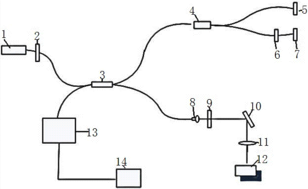
[0020] like figure 1 As shown, the single spectrometer polarization frequency domain optical coherence tomography system based on an optical switch includes a low coherence broadband light source 1, a fiber polarizer 2, a fiber coupling splitter 3, an optical switch 4, a first fiber mirror 5, fiber optic polarization controller 6, second fiber optic reflector 7, collimating mirror 8, 1 / 4 wave plate 9, three-dimensional scanning galvanometer 10, focusing objective lens 11, sample to be tested 12, spectrometer 13 and computer data acquisition equipment 14, all The low-coherent broadband light source 1 is connected to the fiber-coupled splitter 3 through the optical fiber polarizer 2, and the fiber-coupled splitter 3 is respectively connected to the op...


PUM


Abstract

The invention relates to the field of an optical coherence tomography system of a polarizing frequency domain and in particular relates to an optical coherence tomography system of a polarizing frequency domain of a single spectrograph based on a photoswitch. A high speed photoswitch which is divided into two paths is placed in a reference arm light path, time-shared detection of the single spectrograph for interference signals of two channels of horizontal polarization and vertical polarization is realized by means of channel selection of the photoswitch, and the detected two polarization signals are calculated to acquire an intensity image, a fast axis image and a delay image of a sample with double refraction properties. The system provided by the invention is simple in structure; the light path adjusting difficulty is greatly reduced without using a beam splitter prism, and inter-mode interference brought by a polarization beam splitter is also avoided; and meanwhile, polarization imaging can be realized without complicated phase modulation equipment and algorithms.

Description

technical field [0001] The invention relates to the field of polarization frequency-domain optical coherence tomography systems, in particular to a single-spectrometer polarization frequency-domain optical coherence tomography system based on an optical switch. Background technique [0002] Polarization-sensitive optical coherence tomography (OCT) is a new imaging method developed on the basis of traditional OCT imaging technology. polarization information. The development of polarization OCT has always been accompanied by the development of traditional OCT technology. At present, it has changed from time-domain polarization OCT with slower scanning speed to frequency domain polarization (OCT spectrum domain optical coherence tomography, SDOCT) with faster scanning speed, including spectral polarization OCT and swept polarization OCT. When polarized light is incident on the sample to be tested, the polarization properties of the returned light are changed due to the birefr...

Claims


Application Information

Patent Timeline
Patent Type & Authority Applications(China)
IPC IPC(8): G01N21/01G01N21/45G01N21/23
CPCG01N21/01G01N21/23G01N21/45G01N2021/0112
Inventor 何友武李志芳张颖李晖
Owner FUJIAN NORMAL UNIV
Learn More