
SCR injection system testing device and method

A technology of injection system and testing method, which is applied in the direction of electric control of exhaust treatment device, diagnostic device of exhaust treatment device, exhaust treatment, etc. It can solve the problems of incorrect judgment of SCR injection system, lack of experience in SCR injection system, Issues such as the adverse effects of the SCR injection system can improve detection efficiency and accuracy, avoid complexity and blindness, and enhance competitiveness.

Inactive Publication Date: 2017-08-18
WEICHAI POWER CO LTD +1
View PDF6 Cites 10 Cited by
  • Summary
  • Abstract
  • Description
  • Claims
  • Application Information

AI Technical Summary

Problems solved by technology

However, due to the specific conditions required for the system to work, it is difficult to implement it in the service area. In addition, the maintenance personnel lack experience in the SCR injection system, and it is difficult to judge whether it is working normally, resulting in misjudgment of the SCR injection system
[0004] At present, there is no control device that automatically detects whether the SCR injection system of the vehicle is working normally, and it is difficult to realize the post-processing working conditions and judgment basis under normal detection conditions. The current situation has the following shortcomings: the SCR injection system of the vehicle cannot be correctly judged Whether it is normal or not will lead to misjudgment of the components of the SCR injection system; delay the normal operation of the user's vehicle and cause adverse effects on the SCR injection system in the market; make the intact SCR injection system components scrapped, resulting in a waste of resources

Method used


Image

  • SCR injection system testing device and method
  • SCR injection system testing device and method

Examples


Embodiment Construction

[0022] Exemplary embodiments of the present disclosure will be described in more detail below with reference to the accompanying drawings. Although exemplary embodiments of the present disclosure are shown in the drawings, it should be understood that the present disclosure may be embodied in various forms and should not be limited by the embodiments set forth herein. Rather, these embodiments are provided for more thorough understanding of the present disclosure and to fully convey the scope of the present disclosure to those skilled in the art.

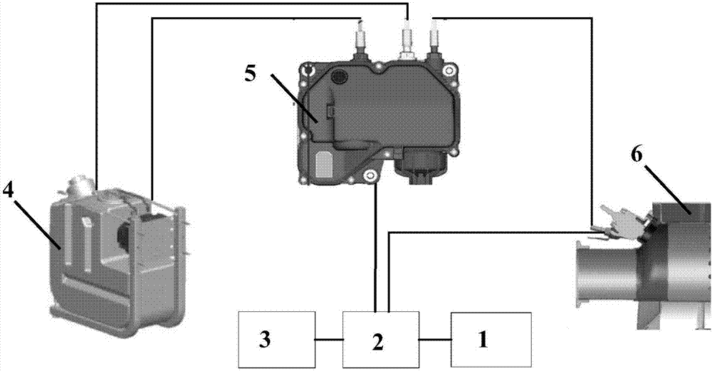
[0023] now refer to figure 1 A test device for an SCR injection system proposed according to an embodiment of the present invention will be described. like figure 1 As shown, the SCR injection system testing device includes a power supply 1, an electronic control unit 2, a display 3, a urea tank 4, a urea pump 5, a nozzle 6 and connecting lines. Among them, the electronic control unit 2 integrates the control program of the SCR i...


PUM


Abstract

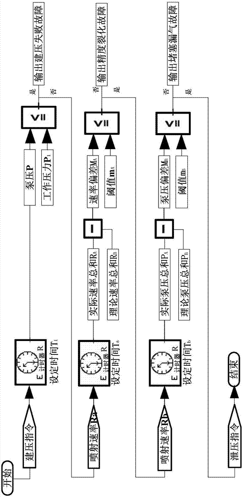
The invention provides a SCR injection system testing device and a method. The method comprises the following steps: (S1) an electronic control unit sends a pressure building instruction to an urea pump of a SCR injection system; the urea pump sucks urea from an urea box of the SCR injection system through an urea pipeline to start the pressure building; the electronic control unit obtains a pressure result through a signal of the urea pump; if a pump pressure P built by the SCR injection system in a set time T1 reaches a working pressure P1, the pressure building is successful; and otherwise, the pressure building failure is output; and (S2) after the working pressure P1 of the urea pump is stabilized, the electronic control unit sends an injection instruction of injecting the urea at an injection speed Ra by a set time Ta to the urea pump; an actual speed sum Ra detected in the set time Ta and a theoretic injection speed sum RA are calculated; the theoretic injection speed sum RA is equal to a product between the injection speed Ra and the set time Ta; if a deviation MA between the theoretic injection speed sum RA and the actual speed sum Ra is not more than a thread mA, the success is achieved; and otherwise, the precision cracking failure of the SCR injection system is output.

Description

technical field [0001] The invention relates to detecting whether an SCR injection system works normally, and in particular relates to a testing device and method for an SCR injection system. Background technique [0002] Selective Catalytic Reduction (Selective Catalytic Reduction, SCR) is the main post-treatment technology for eliminating NOx in diesel engine exhaust. Send instructions to drive the SCR injection system to inject urea solution into the exhaust pipe regularly and quantitatively. The urea solution decomposes into NH3 and CO2 at high temperature. [0003] At present, in the existing technology, the inspection of the SCR injection system is mainly to detect and judge whether the SCR injection system is working normally after artificially manufacturing the detection conditions. According to the working conditions of the SCR injection system, the working state of the SCR injection system is produced, and then the experience of the maintenance personnel is used t...

Claims


Application Information

Patent Timeline
Patent Type & Authority Applications(China)
IPC IPC(8): F01N11/00
CPCF01N11/00F01N2900/0601Y02T10/40
Inventor 李晓光刘钊刘兴龙
Owner WEICHAI POWER CO LTD
Learn More