Multi-stage cylinder line marking and drilling safety tool, multi-stage cylinder line marking method and multi-stage cylinder drilling machining method

A technology for cylindrical workpieces and cylinders, which is applied in the field of multi-level cylindrical scribing and drilling safety tooling and scribing and drilling processing. It can solve the problems of multi-level cylindrical workpiece center of gravity deviation, low processing efficiency, and potential safety hazards, and achieve Reliable assurance of drilling and tapping accuracy, improved processing efficiency, and high safety effects

Pending Publication Date: 2017-08-18
JIANGYIN GIANSUN MOLD
View PDF9 Cites 2 Cited by
  • Summary
  • Abstract
  • Description
  • Claims
  • Application Information

AI Technical Summary

Problems solved by technology

[0002] In the machining of large-scale multi-stage cylindrical workpieces, such as cylindrical workpieces with a diameter of more than 400mm, when marking and drilling on the outer circle, due to the heavy weight of the workpiece, the shift of the center of gravity of the multi-stage cylindrical workpiece, the workpiece cannot be placed stably , Difficult to clamp, inconvenient to move, conventional tooling fixtures have great safety hazards, and safety accidents are prone to occur during the marking process
In the absence of suitable special tooling for scribing and processing, using traditional height gauges and pad irons for operation, it is difficult to guarantee safe production and product processing quality, and the processing efficiency is low, which cannot meet high-quality and efficient processing requirements

Method used


Image

  • Multi-stage cylinder line marking and drilling safety tool, multi-stage cylinder line marking method and multi-stage cylinder drilling machining method

Examples


Embodiment Construction

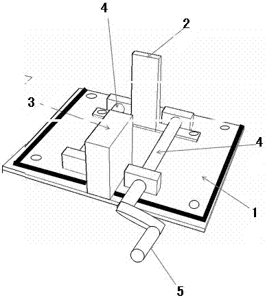
[0018] As shown in the figure, the multi-stage cylinder marking and drilling safety tooling includes a horizontal bottom plate 1; A moving clamping mechanism 3; a pair of parallel horizontal rollers 4 are installed on both sides of the bottom plate, and the two ends of the horizontal rollers are installed on the support through bearings, and at least one end of the horizontal roller 4 is installed with a drive that can drive the horizontal roller. The rocker 5 that the roller rotates; the outer circumference of the cylindrical workpiece can be placed between two horizontal rollers 4 and is tangent to the horizontal rollers, and the axial ends of the cylindrical workpiece can be held by the opposite clamping mechanism 3 and the support baffle 2 Axial clamping fixes or releases. The clamping mechanism adopts a thrust cylinder pneumatic clamping device.

[0019] The multi-stage cylinder marking and drilling processing method of the embodiment of the present invention adopts the ...


PUM


Abstract

The invention belongs to machining devices, and particularly relates to a multi-stage cylinder line marking and drilling safety tool, a multi-stage cylinder line marking method and a multi-stage cylinder drilling machining method. The multi-stage cylinder line marking and drilling safety tool comprises a horizontal base plate. A vertical supporting baffle is fixedly installed on the front portion of the base plate. A clamping mechanism which faces the supporting baffle and can horizontally move forwards and backwards is installed on the rear portion of the base plate. A pair of horizontal rolling shafts which are parallel to each other are installed on the two sides of the base plate, the two ends of each horizontal rolling shaft are installed on supporting bases through bearings, and a rocking handle which can drive the horizontal rolling shafts to rotate is installed at the end of at least one horizontal rolling shaft. The external circumference of a cylindrical workpiece can be installed between the two horizontal rolling shafts and is tangent with the horizontal rolling shafts, and the two axial ends of the cylindrical workpiece can be axially clamped and fixed or released by the clamping mechanism and the supporting baffle facing the clamping mechanism. The multi-stage cylinder line marking and drilling safety tool is simple in structure, high in clamping accuracy, good in stability and high in safety, and convenient to operate and firm to clamp.

Description

technical field [0001] The invention belongs to a mechanical processing device, and in particular relates to a multi-stage cylindrical scribing and drilling safety tooling and a scribing and drilling processing method. Background technique [0002] In the machining of large-scale multi-stage cylindrical workpieces, such as cylindrical workpieces with a diameter of more than 400mm, when marking and drilling on the outer circle, due to the heavy weight of the workpiece, the shift of the center of gravity of the multi-stage cylindrical workpiece, the workpiece cannot be placed stably , Difficult to clamp, inconvenient to move, conventional tooling fixtures have great safety hazards, and safety accidents are prone to occur during the marking process. In the absence of suitable special tooling for scribing and processing, using traditional height gauges and pad irons for operations, it is difficult to guarantee safe production and product processing quality, and the processing ef...

Claims


Application Information

Patent Timeline
Patent Type & Authority Applications(China)
IPC IPC(8): B23Q3/08B23Q17/22B25H7/04
CPCB23Q3/08B23Q17/22B25H7/04
Inventor 李伟平张园
Owner JIANGYIN GIANSUN MOLD
Why Eureka
Try Eureka