
Full-automatic drainage type centrifugal oil purification device

A centrifugal and fully automatic technology, applied in the direction of centrifuges, centrifuges with rotating drums, etc., can solve the problems that the drainage efficiency of oil purification equipment cannot be guaranteed, the working efficiency of oil purification equipment is affected, and the actual production cannot be satisfied. Achieve the effects of cost saving, simple operation and high oil purification efficiency

Pending Publication Date: 2017-08-18
唐山睿泽尔科技有限公司
View PDF0 Cites 5 Cited by
  • Summary
  • Abstract
  • Description
  • Claims
  • Application Information

AI Technical Summary

Problems solved by technology

[0004] 1. It needs to be shut down and operated manually. In the actual operation process, the oil purification equipment will flow the separated impurities and water into the dirt box, and then manually open the valve at the bottom of the dirt box according to the size of the impurities and water to discharge the impurities and water. , this process needs to be shut down, which seriously affects the working efficiency of the oil purification equipment
[0005] 2. If the valve of the dirt receiving box in the oil purification equipment is changed to a solenoid valve, and the switch of the solenoid valve is controlled by the control device at regular intervals or according to the change of the liquid level in the dirt receiving box to realize automatic intermittent drainage, although this process There is no need to shut down the operation, but when the water content in the oil is large, the drainage efficiency of the oil purification equipment cannot be guaranteed, and it cannot meet the needs of actual production

Method used


Image

  • Full-automatic drainage type centrifugal oil purification device
  • Full-automatic drainage type centrifugal oil purification device
  • Full-automatic drainage type centrifugal oil purification device

Examples


Embodiment Construction

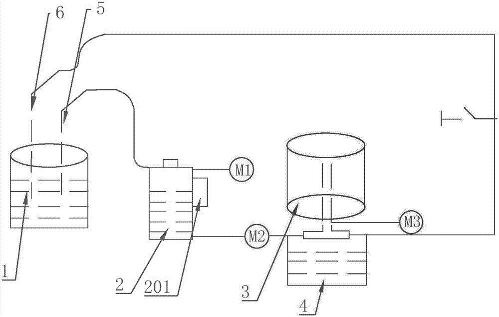
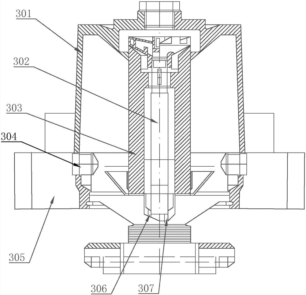
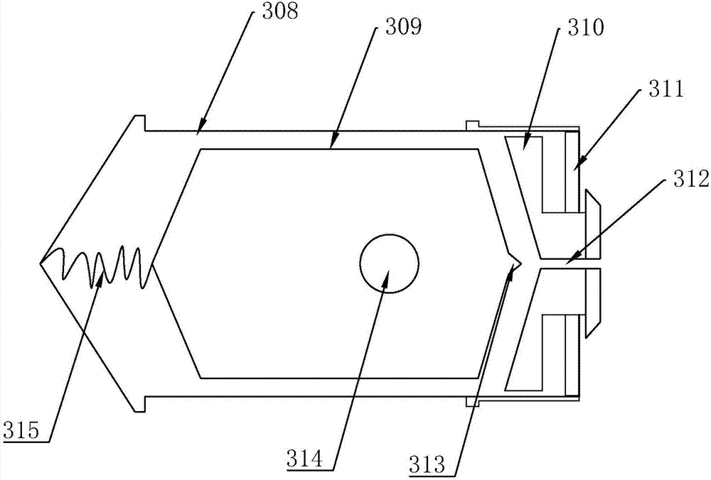
[0028] like Figure 1-4 As shown in the figure, a fully automatic drainage type centrifugal oil purifier of the present invention includes an oil tank 1, a dirt holding box 4 and a centrifugal barrel assembly 3, an auxiliary oil tank 2 is arranged between the oil tank 1 and the centrifugal barrel assembly 3, and the centrifugal barrel assembly 3 Connected to the engine, the auxiliary oil tank 2 and the centrifugal barrel assembly 3 are respectively connected to the booster pump, and the auxiliary oil tank 2 is also connected to the vacuum pump. The centrifugal barrel assembly 3 includes a centrifugal barrel body 301, and the centrifugal barrel body 301 is installed on the central shaft 302. A plurality of bowl-shaped discs 303 placed vertically concentrically upward are installed on the 302. The discs are provided with diversion grooves. The bottom of the centrifugal bucket body 301 is provided with a sewage outlet. The bottom end is provided with an oil inlet 306 and an oil r...


PUM


Abstract

The invention discloses an automatic drainage device which is arranged on the lower portion of a centrifugal barrel body and distributed symmetrically with respect to a center axis. The automatic drainage device comprises a shell with a cavity. A floater is mounted in the shell. A balance spring is arranged between the top end of the floater and the top end of the shell, and the top end of the floater and the top end of the shell are connected through the balance spring. An end cover is arranged at the lower end of the inside of the shell and is mounted at the bottom of the shell through a fastening clamp spring. A water outlet is formed in the end cover. The bottom of the floater and the end cover are matched in structure. An abutting block matched with the water outlet is arranged at the lower end of the bottom of the floater. An appropriate gap is opened for water drainage operation through the floater according to the water volume under the pressure of water and the effect of the balance spring, water in a centrifugal barrel is automatically and continuously drained under the condition of non-stop operation, the airtightness of a centrifugal field is guaranteed, and separation of pollutants and oil liquid in the centrifugal field is not affected; and the displacement can be automatically determined according to the separated water volume, and water is drained in time.

Description

technical field [0001] The invention relates to the field of oil purification, in particular to a fully automatic drainage type centrifugal oil purification device. Background technique [0002] Whether it is the lubricating oil of the lubrication system of the thin oil station, the turbine oil or the hydraulic oil in each hydraulic system, if the oil is mixed with water and mechanical impurities, it will cause serious harm to the normal operation of the mechanical equipment. The failure of lubrication and hydraulic system caused by the pollution of oil and hydraulic oil accounts for more than 65% of all failures of thin oil lubrication and hydraulic system. Therefore, it is necessary to remove pollutants (solid particles, water, gas, etc.) in the oil. ) to ensure the normal working of mechanical equipment. The traditional oil purification methods mainly rely on platen type oil filter, filter type oil filter, vacuum plus filter type oil filter, coalescing type oil filter, e...

Claims


Application Information

Patent Timeline
Patent Type & Authority Applications(China)
IPC IPC(8): B04B1/04B04B7/12B04B7/00B04B15/00
CPCB04B1/04B04B7/00B04B7/12B04B15/00
Inventor 张瑞新孙洁
Owner 唐山睿泽尔科技有限公司
Learn More