Linear vibrator

A linear vibrator and coil technology, applied in electrical components, electromechanical devices, etc., can solve the problems of shortening the service life of the motor, difficult to touch the screen, and achieve the effect of fast response.

Pending Publication Date: 2017-08-15
威海硕科微电机有限公司
View PDF4 Cites 5 Cited by
  • Summary
  • Abstract
  • Description
  • Claims
  • Application Information

AI Technical Summary

Problems solved by technology

Brush series motors using commutators, due to the mechanical friction generated by the brushes when they pass through the commutator segments during rotation, sparks and foreign objects will be generated, which will shorten the service life of the motor
Moreover, it takes a certain amount of time to reach the target vibration amount due to the inertia of the rotation after the motor is turned on, so it is difficult to generate screen touch vibration

Method used


Image

  • Linear vibrator
  • Linear vibrator
  • Linear vibrator

Examples


Embodiment 1

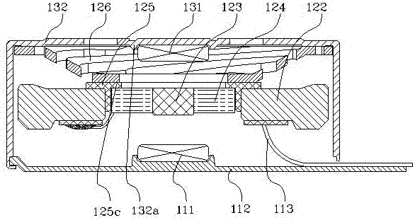
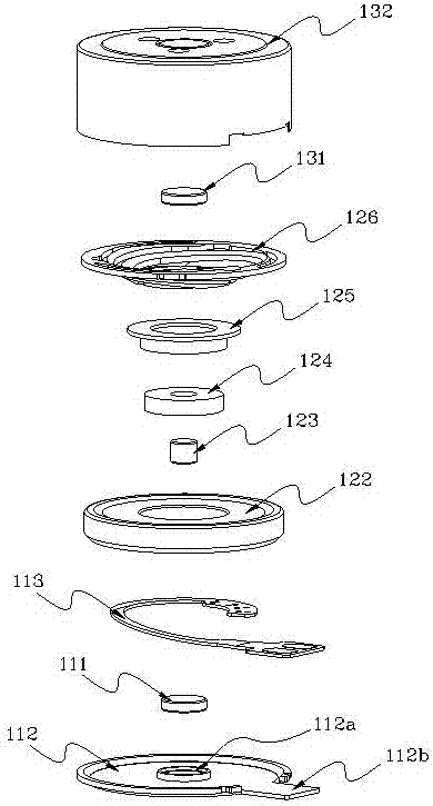
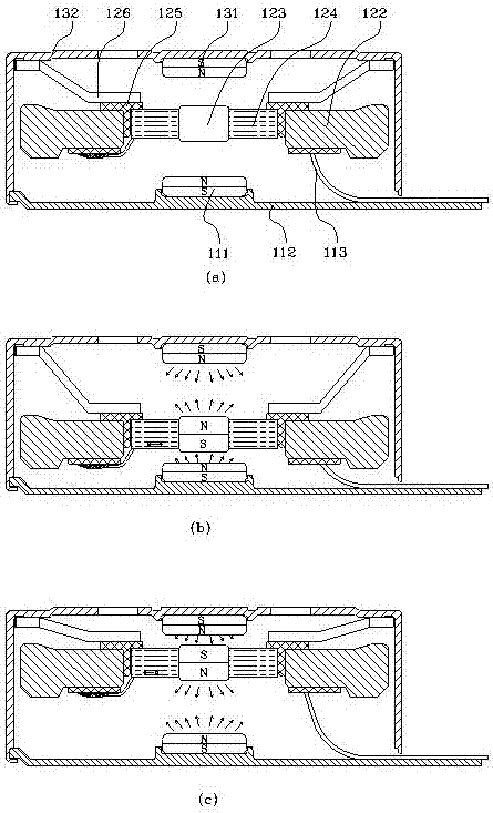
[0029] refer to figure 1 , figure 2 , the linear vibrator of the present invention is made up of the following components: the upper casing 132 that protects the internal components of the linear vibrator and provides space; The electromagnetic force produced by the electromagnet interacts; the upper casing 132 and the first permanent magnet 131 form the upper fixed part 130, and the upper fixed part 130 is connected with the elastic part 126 of the vibrating part 120; the vibrating part 120 includes an iron core support 123, a coil 124, mass body 122, metal plate 125, elastic component 126, the outer diameter of the iron core support 123 is surrounded by the coil 124, the elastic component 126 is connected with the vibrating part 120 through the metal sheet 125; matches with the upper casing 132 to protect the lower part of the internal components Case 112; the second permanent magnet 111 interacting with the electromagnet of the vibrating part 120 is set in the lower case ...

Embodiment 2

[0039] In this embodiment, the metal plate 325 connecting the elastic member 326 and the mass body can be used as a bracket, and the iron steel plate is made into the metal plate 325 by stamping equipment. The metal plate 325 has an annular flat part 325a and A cylindrical protruding part 325b, the elastic member 326 is fixed on the upper surface of the circular planar part 325a, and the cylindrical protruding part 325b is inserted into the inner ring of the coil 324 as a metal body. The cylindrical protruding portion 325b is inserted into the air-core coil 324 , and the same effect can be achieved without inserting the iron core support 123 . In order to maximize the strength of the electromagnet, the height of the cylindrical protrusion 325b ≥ the height of the hollow coil 324 . The coil 324 generates an electromagnetic force in the direction of vertical vibration, and the cylindrical protrusion 325b of the metal plate 325 forces this electromagnetic force in one direction, ...


PUM


Abstract

The invention discloses a linear vibrator. An upper-end fixation part includes an upper case and a first permanent magnet fixed with the upper case. A lower fixation part consists of a lower case, a flexible circuit board, and a second permanent magnet fixed to the lower case. A vibration part includes an elastic part, a hollow coil, a metal plate and a mass body; the elastic part enables the vibration part and the upper case to be connected mutually; the upper case and the lower case form a housing of the linear vibrator to provide internal space. The first permanent magnet and the second permanent magnet are opposed to the upper and lower end surface of the hollow coil respectively and the magnetic properties of the first permanent magnet and the second permanent magnet are identical with the magnetic property of a magnetic pole opposite to the hollow coil. The mass body is arranged at the periphery of the hollow coil; a metal body is arranged in the hollow coil; an external power supply is inputted into the coil by a flexible circuit board; and when the coil is electrified, the metal body becomes an electromagnet. According to the linear vibrator, the metal body inserted into the hollow coil serves as the electromagnet and interacts with the permanent magnets, so that the vibration part moves up and down rapidly to make vibration.

Description

technical field [0001] The invention relates to a linear vibrator, in particular to a linear vibrator applied to a hand-held communication device. Background technique [0002] Recently, there has been a surge in shipments of large-screen LCD mobile phones that are convenient for consumers to use, and most of the large-screen LCD mobile phones adopt the touch screen mode. Vibration motors are used to generate vibrations when touch screens are used. The vibration motor uses the principle of electromagnetic force to convert electromagnetic energy into mechanical energy, and is installed in the mobile phone to transmit signals in a silent manner. [0003] In the prior art, the rotating part of the unbalanced mass is rotated by generating rotational force to obtain mechanical vibration, such as the contact between the brush (Brush) and the commutator (Commutator) to produce a rectification effect, thereby obtaining the rotational force in the form of mechanical vibration . Br...

Claims


Application Information

Patent Timeline
Patent Type & Authority Applications(China)
IPC IPC(8): H02K33/18
CPCH02K33/18
Inventor 李相宜董慧慧
Owner 威海硕科微电机有限公司
Why Eureka
Try Eureka