
Method and system for performing laser cutting on light filter plate

A laser cutting and optical filter technology, which is applied in laser welding equipment, welding/welding/cutting items, manufacturing tools, etc., can solve the problems of anti-reflection coating on the surface of large optical filters, damage to cutting channels, etc. The effect of chip rate, loss reduction, uniform fracture surface without taper

Active Publication Date: 2017-08-11
东莞市盛雄激光先进装备股份有限公司
View PDF8 Cites 13 Cited by
  • Summary
  • Abstract
  • Description
  • Claims
  • Application Information

AI Technical Summary

Problems solved by technology

[0004] In view of this, the present invention provides a method and system for laser cutting optical filters to solve the problems in the prior art that the anti-reflection coating on the surface of the optical filter is damaged and the cutting channel is wide due to the large laser focus spot

Method used


Image

  • Method and system for performing laser cutting on light filter plate
  • Method and system for performing laser cutting on light filter plate
  • Method and system for performing laser cutting on light filter plate

Examples


Embodiment Construction

[0045] The following will clearly and completely describe the technical solutions in the embodiments of the present invention with reference to the accompanying drawings in the embodiments of the present invention. Obviously, the described embodiments are only some, not all, embodiments of the present invention. Based on the embodiments of the present invention, all other embodiments obtained by persons of ordinary skill in the art without making creative efforts belong to the protection scope of the present invention.

[0046] An embodiment of the present invention provides a method for laser cutting an optical filter. The optical filter is preferably a blue glass filter, which filters out infrared light in visible light by absorbing infrared light. Of course, the present invention is not limited thereto , in other embodiments, the filter may also be a filter for filtering infrared light in visible light by reflecting infrared light.

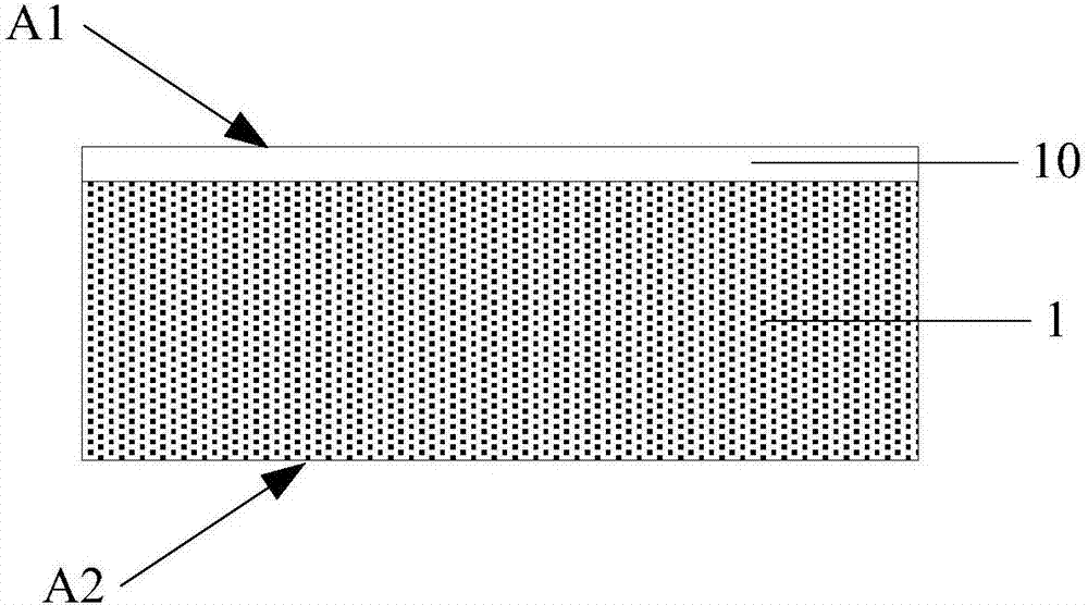
[0047] Further, as figure 1 As shown, t...


PUM

PropertyMeasurementUnit
lengthaaaaaaaaaa
diameteraaaaaaaaaa

Abstract

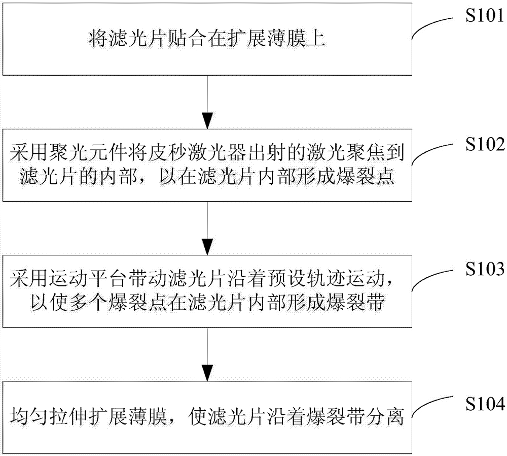
The invention provides a method and a system for performing laser cutting on a light filter plate. The method comprises the following steps of: adhering the light filter plate on a spreading film; focusing laser emitted by a picoseconds laser unit inside the light filter plate by a light focusing element to form bursting points inside the light filter plate; and driving the light filter plate to move along a preset path through a motion platform, and forming a bursting zone inside the light filter plate by the bursting points; uniformly stretching and spreading the film, and separating the light filter plate along the bursting zone. According to the method provided by the invention, focused laser spots are relatively small, and therefore, the width of the formed bursting zone, namely a cutting channel is relatively small, loss of materials can be reduced, and the strip yield is increased; and moreover, the distance from the bursting zone to the first surface and the distance from the bursting zone to the second surface are greater than or equal to a first preset value, and therefore, an antireflection film on the surface is not damaged; besides, the film uniformly stretches and spreads, so that the bursting zone inside the light filter plate spreads towards upper and lower surfaces to realize plate splitting and separating, and therefore, the fracture surface of the light filter plate is uniform without taper.

Description

technical field [0001] The present invention relates to the technical field of laser cutting, in particular to a method and system for laser cutting optical filters. Background technique [0002] Most of the existing mobile phone cameras use blue glass filters to absorb infrared light to filter out the infrared light in the visible light entering the lens, so as to prevent the infrared light from affecting the quality of the captured image. Furthermore, in order to increase the light transmittance of the blue glass filter and improve the brightness of the captured image, an anti-reflection film is also attached to the surface of the filter in the prior art. [0003] Before applying the above-mentioned optical filter to the mobile phone camera, the optical filter needs to be cut so that the size of the optical filter can meet the requirements of the camera. The prior art discloses a method of cutting an optical filter attached with an anti-reflection film by using a laser. H...

Claims


Application Information

Patent Timeline
Patent Type & Authority Applications(China)
IPC IPC(8): B23K26/38B23K26/402B23K26/0622
CPCB23K26/0624B23K26/38B23K26/402B23K2103/54
Inventor 陶雄兵李万朋李光辉韦超
Owner 东莞市盛雄激光先进装备股份有限公司
Learn More