A power-driven two-phase loop active regulation energy storage and release system and method

A power-driven, phase-loop technology, applied in thermal storage equipment, lighting and heating equipment, indirect heat exchangers, etc. Lack of initiative and other problems, to achieve the effect of ensuring active control performance, simple structure, and improving flow characteristics

Active Publication Date: 2019-09-20
TSINGHUA UNIV
View PDF10 Cites 0 Cited by
  • Summary
  • Abstract
  • Description
  • Claims
  • Application Information

AI Technical Summary

Problems solved by technology

Heat storage materials exchange heat directly with cold and heat sources. This technology has certain limitations in terms of space for energy sources and users. Sensible heat transfer using water as a working medium is currently a relatively mature heat storage and heat release method. Due to the low efficiency of the heat transfer process characterized by obvious heat transfer, in order to meet the heat transfer capacity, the flow rate of the working medium is often required to be large, resulting in high power consumption of the system, and the isothermal heat transfer cannot be achieved during the heat transfer process, resulting in the phase change material Uneven solidification and melting in the accumulator affects energy storage and energy storage efficiency; heat pipe is one of the most effective heat transfer technologies, but affected by the form of power, it is a passive heat transfer process, which is suitable for long-distance and There are still difficulties in complex pipeline network transportation, and there is a lack of initiative in energy regulation

Method used


Image

  • A power-driven two-phase loop active regulation energy storage and release system and method
  • A power-driven two-phase loop active regulation energy storage and release system and method

Examples


Embodiment Construction

[0024] The present invention will be further described below in conjunction with accompanying drawing and specific embodiment:

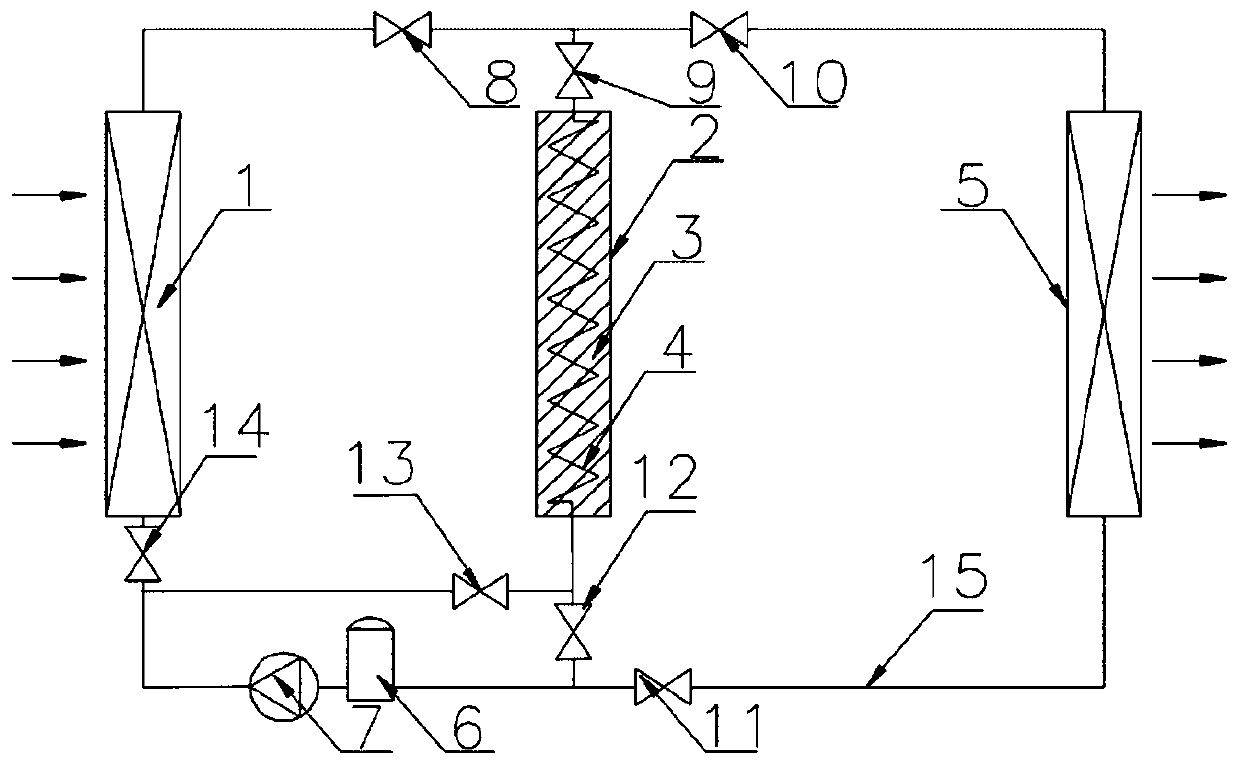
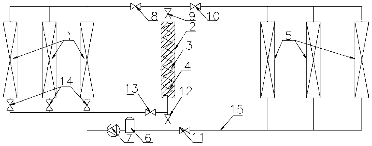
[0025] figure 1 It is a schematic diagram of the principle and structure of a power-driven two-phase loop active regulation energy storage and release system, including source side heat exchanger 1, accumulator 2, energy storage material 3, energy storage heat exchanger 4, user side Heat exchanger 5, liquid reservoir 6, power unit 7, first valve 8, second valve 9, third valve 10, fourth valve 11, fifth valve 12, sixth valve 13 and seventh valve 14; The source-side heat exchanger 1, the energy-storage heat exchanger 4, the user-side heat exchanger 5, the liquid reservoir 6 and the power unit 7 form a closed loop space through the connecting pipeline 15 and corresponding valves, and its interior is filled with Inject liquid low boiling point fluid working medium. The energy storage material 3 can be one of paraffin, sodium sulfate decahydrate, or bis...


PUM


Abstract

The invention provides a power-driven two-phase loop active regulation and control type energy storage and release system and method. The system comprises a source side heat exchanger, an energy accumulator, a user side heat exchanger, a liquid storage device, a power device and valves. The parts are connected with the valves to form a closed loop space through pipelines, and a low-boiling-point fluid working medium is injected in the closed loop space. The method includes five operation modes, namely, the source side direct heat supply mode, the source side energy storage mode, the source side direct heat supply and source side energy storage mode, the energy accumulator heat supply mode and the source side direct heat supply and energy accumulator heat supply mode. Compared with a sensible heat energy storage and release system, the injection amount of a heat-transfer medium can be greatly decreased, the operation cost of the device is reduced, and the operation efficiency is improved. Compared with a heat pipe energy storage and release system, due to the addition of the power device, the flowing characteristic of the low-boiling-point working medium in the system is improved, the active regulation and control performance of the energy storage and release system is easy to control, long-distance and complex pipe network heat transportation can be achieved, and the power-driven two-phase loop active regulation and control type energy storage and release system and method are safer and more reliable.

Description

technical field [0001] The invention belongs to the technical field of energy storage and utilization and active regulation, in particular to an active energy storage and release system based on a power-driven two-phase loop. Background technique [0002] Improving energy efficiency and protecting the environment have become important issues to be solved in today's society. Energy gradient utilization is currently one of the important measures to improve energy utilization and protect the environment. In existing distributed energy systems and industrial waste heat recovery, due to changes in user loads, system energy utilization does not match and the system’s operating performance under full working conditions Energy storage and energy release technology is an effective way to solve the complementary matching between energy utilization and user load changes. Improving the energy storage and release operating efficiency of the energy storage system, reducing system operati...

Claims


Application Information

Patent Timeline
Patent Type & Authority Patents(China)
IPC IPC(8): F28D20/02F28F27/00
CPCF28D20/021F28D20/028F28D2021/0035F28D2021/0068F28F27/00Y02E60/14
Inventor 史琳马跃征冯乐军陈静
Owner TSINGHUA UNIV
Why Eureka
Try Eureka