
Air monitoring system and air monitoring method

A technology of air monitoring and monitoring control, which is applied in the direction of measuring devices, analyzing gas mixtures, and the structural details of gas analyzers. Monitoring the Effects of Data Quality

Inactive Publication Date: 2017-08-04
广东省环境监测中心
View PDF0 Cites 2 Cited by
  • Summary
  • Abstract
  • Description
  • Claims
  • Application Information

AI Technical Summary

Problems solved by technology

In summary, the above two methods have failed to fundamentally solve the problem of mutual interference when checking and calibrating

Method used


Image

  • Air monitoring system and air monitoring method
  • Air monitoring system and air monitoring method
  • Air monitoring system and air monitoring method

Examples


Embodiment 1

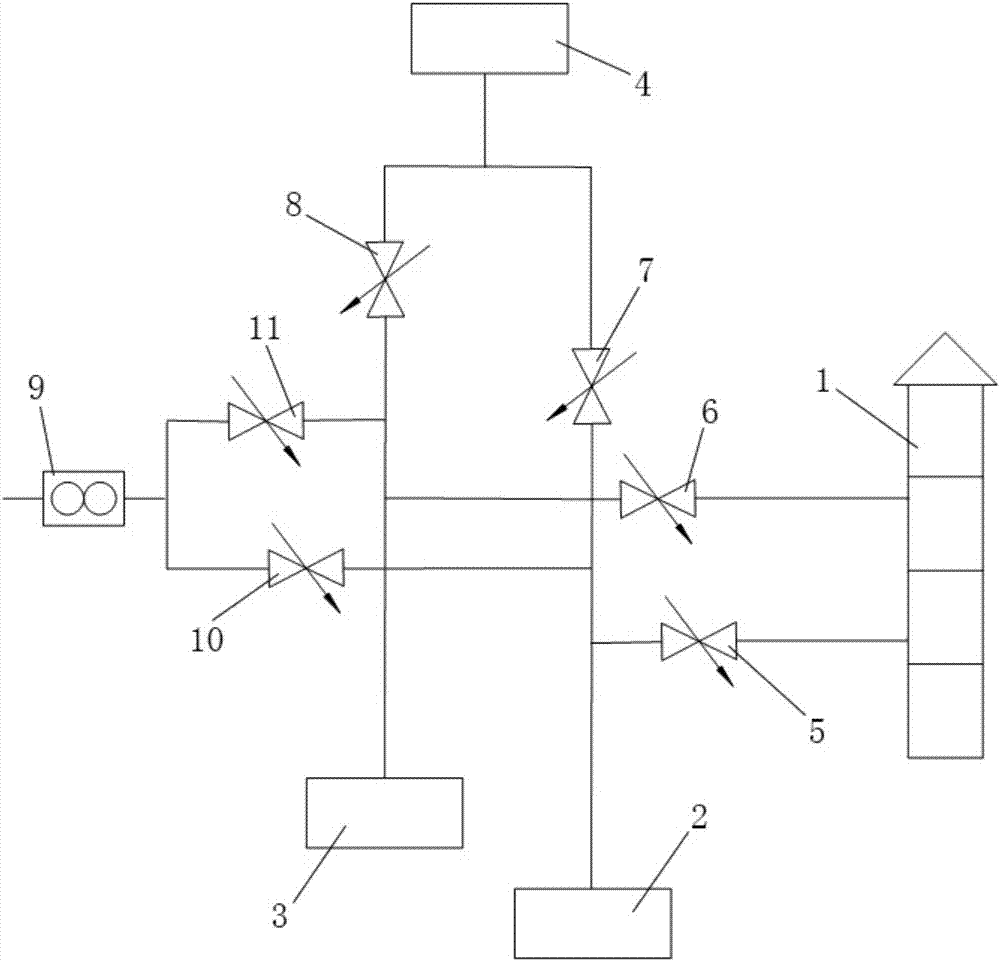
[0037]An air monitoring system, comprising a plurality of air monitoring devices and a monitoring control platform for collecting the detection results of each air monitoring device, the air monitoring device includes a sample gas main pipe 1, a first detection instrument 2, a second detection instrument 3, a calibration gas The generating device 4, the first sample gas switching valve 5, the second sample gas switching valve 6, the first calibration gas switching valve 7 and the second calibration gas switching valve 8, the sample gas main pipe is connected with the first sample gas switching valve and the The second sample gas switch valve is connected, the first sample gas switch valve is connected with the first detection instrument, and the second sample gas switch valve is connected with the second detection instrument;

[0038] The calibration gas generating device is respectively connected with the first calibration gas switching valve and the second calibration gas swi...

Embodiment 2

[0052] A method for air monitoring using the air monitoring system described in Embodiment 1, comprising the following steps:

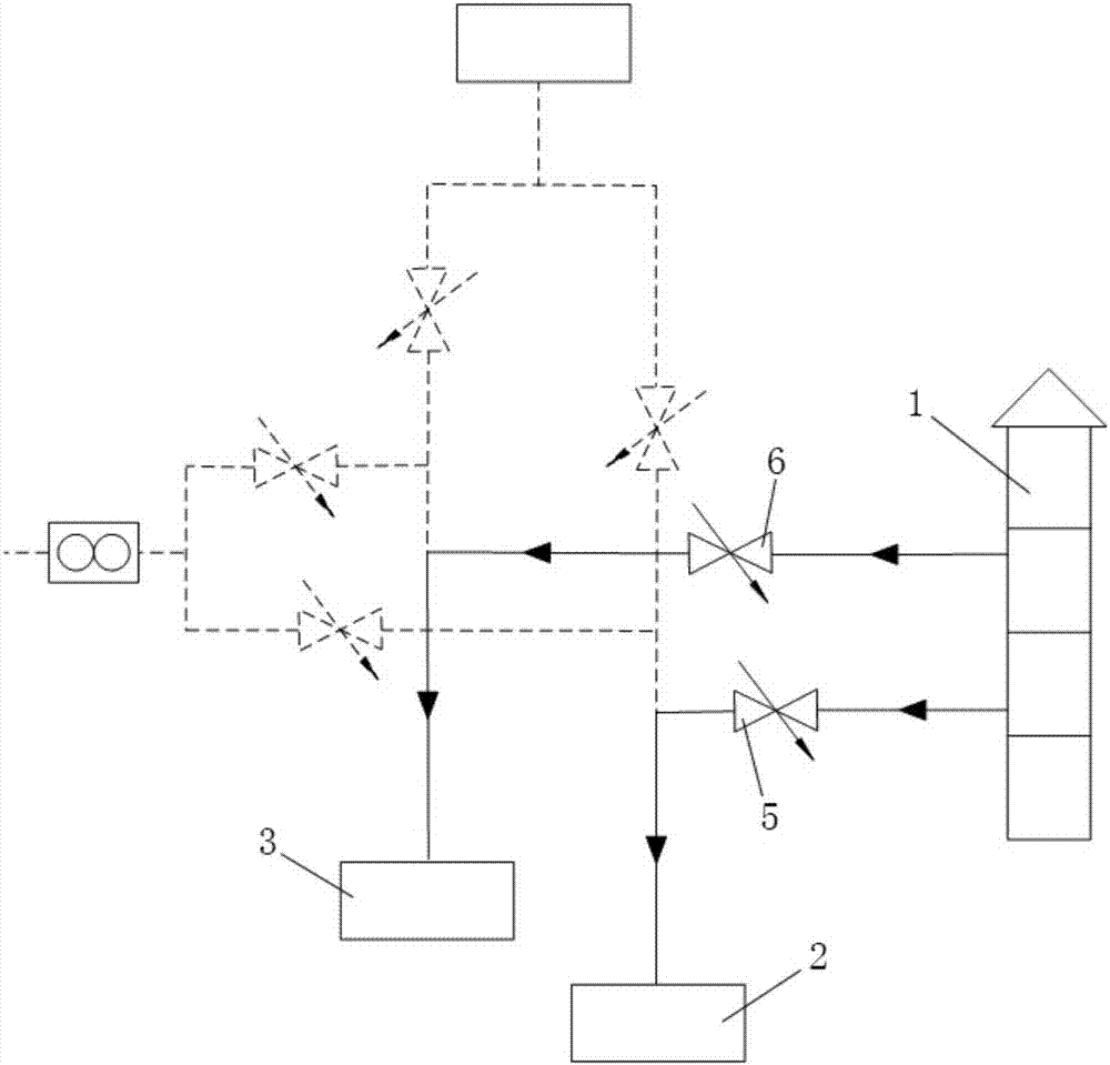
[0053] When sampling is required, open the first sample gas switching valve and the second sample gas switching valve, close the first calibration gas switching valve and the second calibration gas switching valve, and the sample gas main pipe will input the sample gas to the first detection instrument respectively and the second detection instrument, the first detection instrument and the second detection instrument respectively detect the input sample gas and send the detection results of the air monitoring device to the monitoring and control platform;

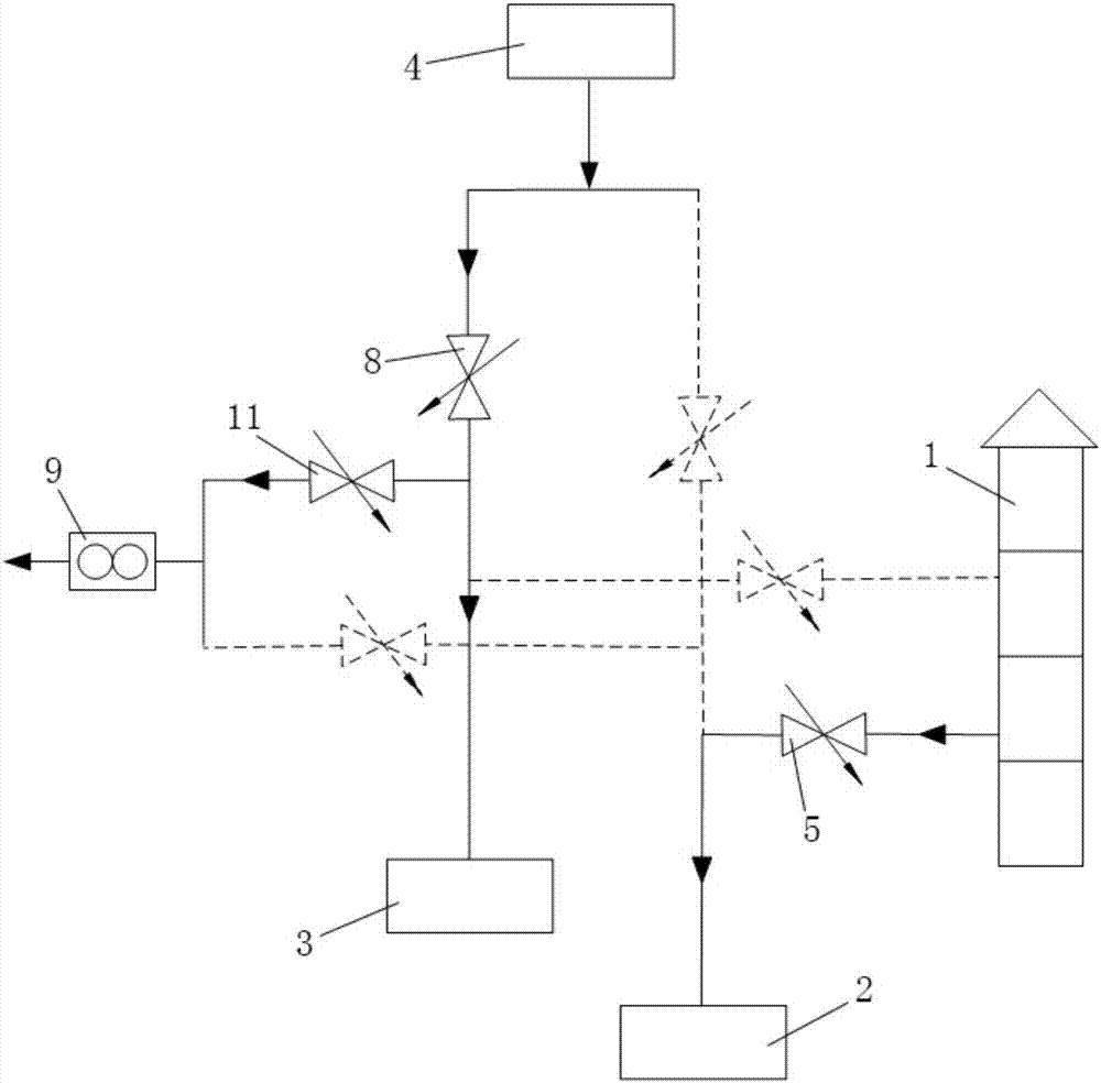
[0054] When calibration is required, the calibration gas generating device inputs the calibration gas. If the first detection instrument is required to calibrate, the first calibration gas switching valve is opened and the first sample gas switching valve is closed, so as to prevent the incoming cal...


PUM


Abstract

The invention discloses an air monitoring system and a monitoring method thereof, wherein the air monitoring system includes a plurality of air monitoring devices and a monitoring control platform for collecting the detection results of each air monitoring device, and the air monitoring device includes a sample gas main pipe , the first detection instrument, the second detection instrument, the calibration gas generating device, the first sample gas switch valve, the second sample gas switch valve, the first calibration gas switch valve and the second calibration gas switch valve, the sample gas main pipe is connected with The first sample gas switching valve is connected to the second sample gas switching valve, the first sample gas switching valve is connected to the first detection instrument, and the second sample gas switching valve is connected to the second detection instrument. The invention not only effectively avoids mutual interference during gas inspection and calibration, but also can check whether there is an air leakage problem in the pipeline, which can greatly improve the effective data acquisition rate of the air monitoring system, and then improve the online monitoring data of the environmental monitoring management department. quality.

Description

technical field [0001] The invention relates to the field of environmental monitoring, in particular to an air monitoring system and a monitoring method thereof. Background technique [0002] According to the relevant regulations on the operation and management of the National Ambient Air Automatic Monitoring Station (hereinafter referred to as "air station"), the air station needs to regularly check / calibrate the SO 2 , O 3 , NO 2 and CO analyzers. The quality control requirements implemented at this stage are: zero-span inspection and calibration is carried out every day, and the frequency of inspection and calibration is high. According to the construction department, the air stations are divided into national control points, provincial control points, city control points, etc. At present, there are as many as 1436 air stations in the country, and the number is still increasing year by year. Gas analysis is common. The problems of mutual interference during the inspec...

Claims


Application Information

Patent Timeline
IPC IPC(8): G01N33/00
CPCG01N33/0009G01N33/0032
Inventor 张涛周炎岳玎利区宇波江明
Owner 广东省环境监测中心
Learn More