
Improved steel pipe clamping device with horizontal adjustment function

A clamping device and level adjustment technology, applied in positioning devices, clamping, manufacturing tools, etc., can solve the problems of random adjustment of clamping, easy to loose and fall, and the firmness cannot be further guaranteed. Holds the steel pipe firmly, is convenient for cleaning and finishing, and has the effect of flexible processing

Inactive Publication Date: 2017-08-04
陈加奎
View PDF0 Cites 7 Cited by
  • Summary
  • Abstract
  • Description
  • Claims
  • Application Information

AI Technical Summary

Problems solved by technology

Ordinary ordinary mechanical clamping devices use a single screw tightening method to achieve the task of clamping parts, including the existing steel tube vise clamping device, whose clamping firmness cannot be further improved Guaranteed, it is very easy to loosen and drop the steel pipe during the clamping process. Secondly, the existing clamping device generally adopts a fixed structure up and down to realize the clamping work of the steel tube, which leads to the clamping of the steel tube. The holder cannot be adjusted at will according to different process requirements, so what is needed at this stage is a device that can clamp steel pipes more firmly, clamp steel pipes with more types, and can adjust the height of clamped steel pipes at will to meet social needs. need

Method used


Image

  • Improved steel pipe clamping device with horizontal adjustment function

Examples


Embodiment Construction

[0017] Below in conjunction with accompanying drawing and embodiment the present invention is described in further detail:

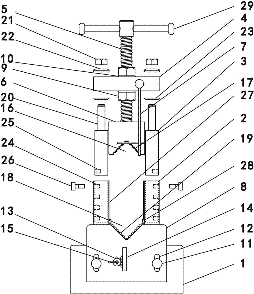
[0018] As an embodiment of the improved steel pipe clamping device with horizontal adjustment in the present invention, such as figure 1 As shown, it includes a base 1, a sleeve rod 2, a lifting rod 3, a cross bar 4, a screw rod 5, an upper clamping head 6, an elevation rod 7, a lower clamping head 8 and a fine-tuning assembly (not shown in the figure). The bottom of the base 1 is larger than the top of the base 1, the sleeve rods 2 are arranged on the left and right sides of the base 1, and the inside of the sleeve rods 2 is provided with vertical holes (not shown in the figure), so The elevating rod 3 is arranged inside the vertical opening (not shown in the figure), the cross bar 4 is arranged on the top of the elevating rod 3, and the middle part of the cross bar 4 is provided with a first through hole (fig. not shown), the screw rod 5 passes throug...


PUM


Abstract

The invention relates to the technical field of machining devices, in particular to an improved steel pipe clamping device with a horizontal adjustment function. The improved steel pipe clamping device comprises a base, sleeve rods, lifting rods, a transverse rod, a spiral rod, an upper clamping head, an elevation rod, a lower clamping head and a fine adjustment assembly. The bottom of the base is larger than the upper portion of the base. The sleeve rods are arranged on the left side and the right side of the base. Vertical open holes are formed inside the sleeve rods. The lifting rods are arranged inside the vertical open holes. The transverse rod is arranged on the upper portion of the lifting rods. The upper clamping head is arranged at the lower end of the spiral rod. The elevation rod is arranged one side of the transverse rod. The lower clamping head is arranged on the two sides of the base. Fixed columns are arranged on the base. Grooves are formed in the lower clamping head. The grooves are sleeved with the fixed columns. A rotating gear is further arranged on the base, and a vertical gear strip is arranged on the lower clamping head.

Description

technical field [0001] The invention relates to the technical field of mechanical processing devices, in particular to an improved steel pipe clamping device with horizontal adjustment. Background technique [0002] With the continuous development of machining technology, machine tools are used more and more, especially some clamping devices are used more widely. Ordinary ordinary mechanical clamping devices use a single screw tightening method to achieve the task of clamping parts, including the existing steel tube vise clamping device, whose clamping firmness cannot be further improved Guaranteed, it is very easy to loosen and drop the steel pipe during the clamping process. Secondly, the existing clamping device generally adopts a fixed structure up and down to realize the clamping work of the steel tube, which leads to the clamping of the steel tube. The holder cannot be adjusted at will according to different process requirements, so what is needed at this stage is a d...

Claims


Application Information

Patent Timeline
Patent Type & Authority Applications(China)
IPC IPC(8): B23Q3/06
CPCB23Q3/064
Inventor 陈加奎
Owner 陈加奎
Learn More