
Printing device

By implementing the reciprocating motion of the winding unit and the design of drying components in the printing equipment, the problem of insufficient drying speed of traditional printing equipment is solved, printing efficiency and space utilization are improved, and operator workload and risk of material damage are reduced.

Active Publication Date: 2017-08-01
KOSTECH INC
View PDF7 Cites 2 Cited by
  • Summary
  • Abstract
  • Description
  • Claims
  • Application Information

AI Technical Summary

Problems solved by technology

However, since such a large dryer D takes up a considerable amount of installation space, only a relatively small number of printing devices can be accommodated in a predetermined space
Therefore, the dryer may be inefficient in terms of productivity, and further a problem that the dryer cannot be installed in a small installation space at all may occur

Method used


Image

  • Printing device
  • Printing device
  • Printing device

Examples


Embodiment Construction

[0036] When adding reference numerals to components of each drawing, although the same components are shown in different drawings, it should be noted that these components should have the same numerals as much as possible. Also, in describing the present disclosure, when it is determined that the gist of the present disclosure may be unclear due to detailed description of known configurations or functions involved, the detailed description of the known configurations or functions will be omitted.

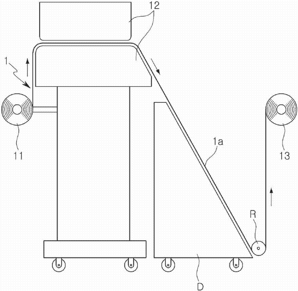
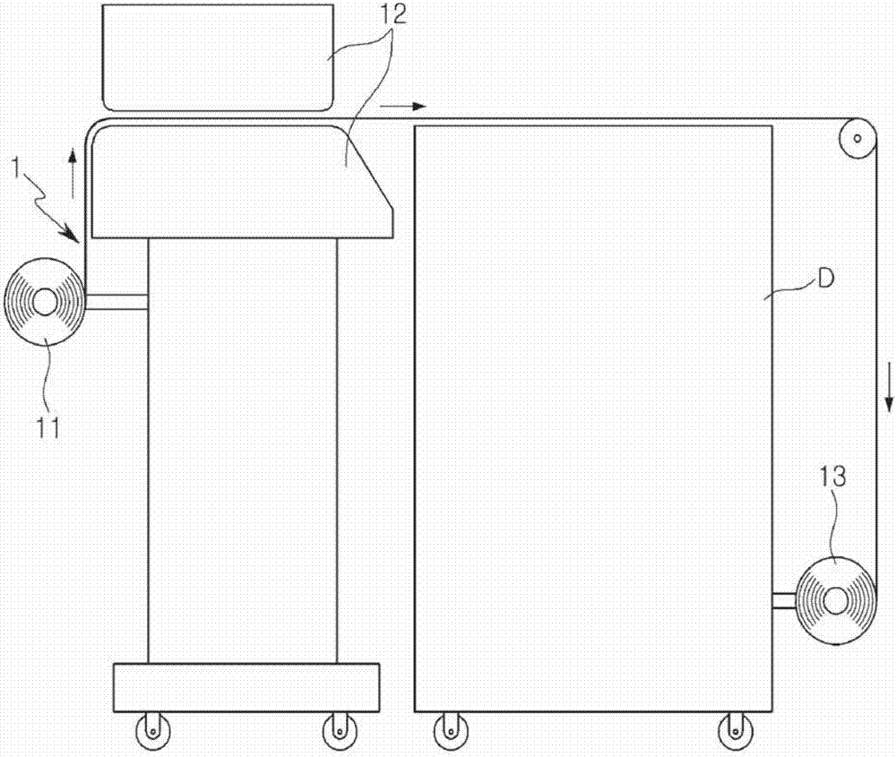
[0037] image 3 is a schematic diagram of a printing apparatus according to an exemplary embodiment in the present disclosure, Figure 4 with Figure 5 based on image 3 A view of a mobile device of a different exemplary embodiment of a printing apparatus.

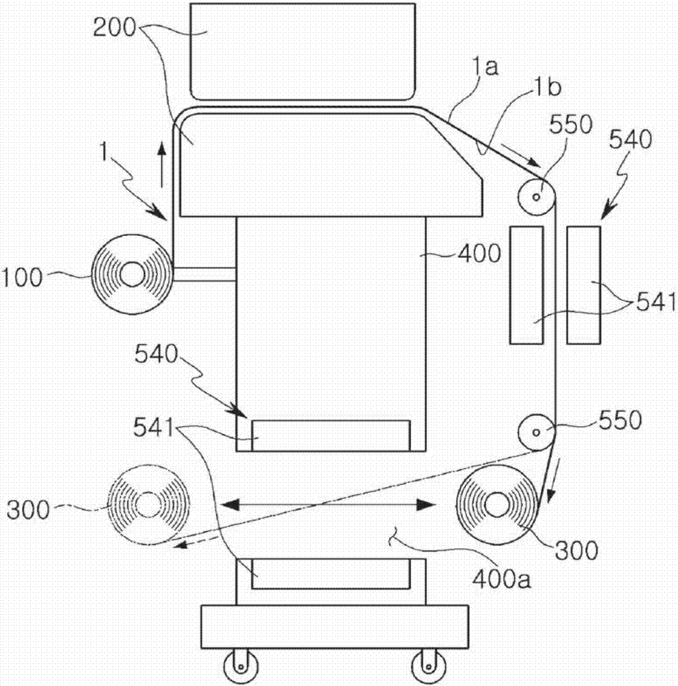
[0038] in addition, Image 6 based on image 3 A view of the drying unit of a different exemplary embodiment of a printing apparatus.

[0039] Referring to the drawings, the printing apparatus may include a main body for p...


PUM


Abstract

A printing device according to the present invention comprises: a main body having a printing unit for printing on a material, and a winding unit for winding the material on which printing was performed; and a moving means provided at the main body, and provided to allow the winding unit to reciprocate between an output side space and an input side space of the printing unit.

Description

technical field [0001] This disclosure relates to printing devices and in particular to printing devices for printing text or images on material. Background technique [0002] In the printing market, traditional manual work has rapidly changed to digital printing technology, and the printing output speed has been rapidly increased due to the improvement of printing equipment manufacturing technology. [0003] However, the drying speed of the printed output may not keep up with the faster printed output speed than before. Therefore, in the event of staining, contamination, and the like, the output may be damaged or lost. [0004] To improve this, different types of dryers have been developed, but the drying speed may be slow so that the drying efficiency may also be low. Furthermore, since the dryer takes up a large amount of installation space, space utilization may be insufficient. As noted above, many complex issues remain. [0005] Specifically, as an exemplary embodi...

Claims


Application Information

Patent Timeline
Patent Type & Authority Applications(China)
IPC IPC(8): B41J11/00B41J15/00B41J15/04B41J15/16F16H19/04F16H1/16F16H7/02G01L5/04
CPCB41J11/002B41J15/00B41J15/04B41J15/042B41J15/046B41J15/16F16H1/16F16H7/02F16H19/04G01L5/04B41J3/4078B41J11/0021B41J11/00216B41J11/0022
Inventor 闵庚元
Owner KOSTECH INC
Learn More