
Tunnel secondary lining rebar positioning, laying and ejecting device

A technology for ejecting devices and tunnels, which is applied in the direction of tunnel lining, tunnel, shaft lining, etc. It can solve the problems of inconvenient positioning of circumferential steel bars, low positioning efficiency, and deformation of circumferential steel bars, so as to facilitate accurate laying and jacking Out, reduce the probability of deformation, reduce the effect of the probability of deformation

Pending Publication Date: 2017-08-01
龚岗
View PDF9 Cites 8 Cited by
  • Summary
  • Abstract
  • Description
  • Claims
  • Application Information

AI Technical Summary

Problems solved by technology

Due to the long size of the hoop steel bar (9-30m) and heavy weight, it will swing or swing during transportation, which is very inconvenient for workers to lift the hoop bar to the longitudinal bar for positioning, and every time they lift the hoop bar Only 1-2 steel bars can be lifted for positioning, and the positioning efficiency is not high. In addition, due to the limited space in the process of lifting the hoop steel bars, the operation is very inconvenient, and it is easy to deform the hoop steel bars due to uneven force. , which is not conducive to precise positioning

Method used


Image

  • Tunnel secondary lining rebar positioning, laying and ejecting device
  • Tunnel secondary lining rebar positioning, laying and ejecting device
  • Tunnel secondary lining rebar positioning, laying and ejecting device

Examples


Embodiment Construction

[0022] The present invention will be described in further detail below by means of specific embodiments:

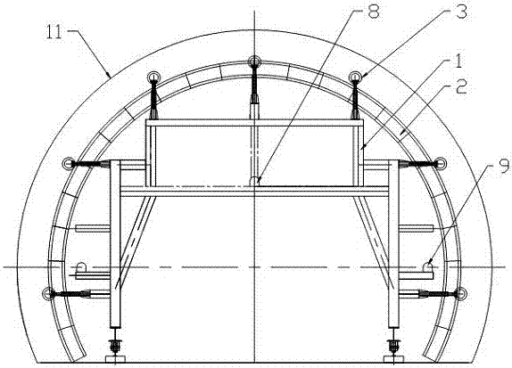
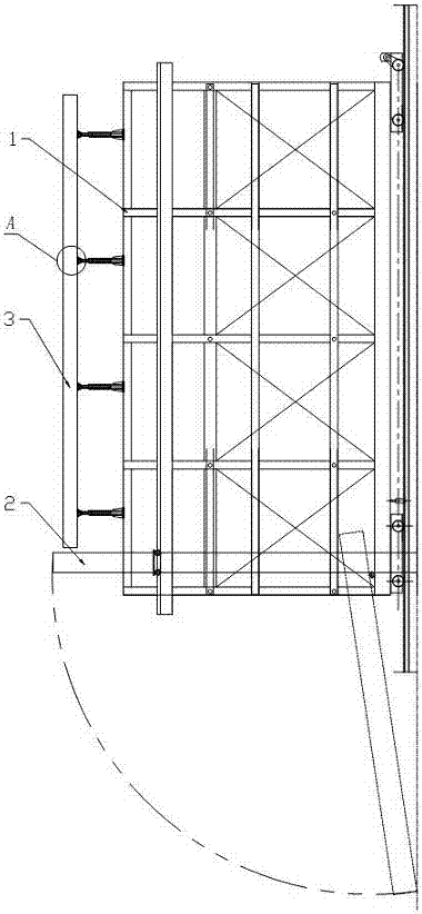
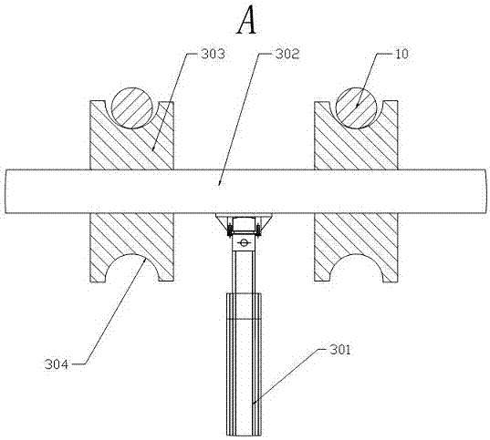
[0023] The reference signs in the drawings of the description include: stand 1, container 2, ejector 3, screw screw ejector 301, ejector rod 302, positioning wheel 303, groove 304, commutator 4, steering Device 5, connecting rod 6, motor 7, vertical line throwing instrument 8, horizontal line throwing instrument 9, hoop steel bar 10, tunnel 11.

[0024] The positioning, laying and ejection devices of the second lining of the tunnel in the embodiment are basically as attached figure 1 And attached figure 2 Shown: including the platform 1 and the positioning mechanism arranged on the platform 1, the laying mechanism and the ejection mechanism, the positioning mechanism includes the vertical positioning cylinder vertically arranged at the bottom of the platform 1 and the vertical positioning cylinder horizontally arranged on both sides of the vertical positioning cylinder ...


PUM


Abstract

The invention relates to the field of tunnel construction auxiliary means, in particular to a tunnel secondary lining rebar positioning, laying and ejecting device. The tunnel secondary lining rebar positioning, laying and ejecting device comprises a rack, a positioning mechanism, a laying mechanism and an ejecting mechanism, wherein the positioning mechanism, the laying mechanism and the ejecting mechanism are arranged on the rack. The positioning mechanism comprises a perpendicular positioning cylinder and a horizontal positioning cylinder; the laying mechanism comprises a container, and the container is parallel to the circumferential direction; the ejecting mechanism comprises a plurality of ejectors arranged in the circumferential direction of the rack, and each ejector comprises a plurality of spiral screw rod ejecting units and connecting rods arranged in the longitudinal direction of the rack; each spiral screw rod ejecting unit comprises an ejecting end and an input end, the input ends of each two adjacent spiral screw rod ejecting units of each ejector are connected through the connecting rods, and motors are connected with the connecting rods; and the ejecting ends of the spiral screw rod ejecting units of each ejector are jointly connected with an ejecting rod, and a plurality of rotatable positioning wheels are arranged on each ejecting rod. According to the tunnel secondary lining rebar positioning, laying and ejecting device, a rebar auxiliary laying device is provided, tunnel secondary lining rebar is laid rapidly and efficiently, and deformation of a circumferential rebar caused by uneven stress is avoided.

Description

technical field [0001] The invention relates to the field of tunnel construction auxiliary tools. Background technique [0002] In the construction of tunnel engineering, the precise positioning of the secondary lining reinforcement binding has always been a major problem restricting the construction quality of the secondary lining. The secondary lining reinforcement includes longitudinal (along the direction of tunnel excavation) reinforcement and circumferential reinforcement (along the tunnel cross-section direction). The structure is very simple, and its function is only a movable scaffold. The steel bar binding is mainly done manually, and the 9-30m long steel bar welded on the ground (or sleeve connection) is sent from the side of the trolley to the arch. And use the elasticity of the steel bar (generally 22-25mm in diameter) to form a ring on the outside of the trolley. Since it is inconvenient to penetrate the tarpaulin to add support points to the steel bars, and ...

Claims


Application Information

Patent Timeline
IPC IPC(8): E21D11/14E21D11/40
CPCE21D11/14E21D11/40
Inventor 龚岗
Owner 龚岗
Learn More