Liquid dynamic pressure suspension mechanical pump

A hydrodynamic and mechanical pump technology, applied in the field of mechanical pumps, can solve the problems of restricting the service life of micro pumps and increasing bearing loads

Active Publication Date: 2017-07-28
HUAZHONG UNIV OF SCI & TECH
View PDF6 Cites 3 Cited by
  • Summary
  • Abstract
  • Description
  • Claims
  • Application Information

AI Technical Summary

Problems solved by technology

In order to improve the power-to-mass ratio of the micro-pump and make the hydraulic components under the micro-size output more pumping work, it is necessary to further increase the impeller speed, resulting in the doubled load on the bearing
Due to the above reasons, mechanical contact bearings seriously restrict the service life of micropumps

Method used


Image

  • Liquid dynamic pressure suspension mechanical pump
  • Liquid dynamic pressure suspension mechanical pump
  • Liquid dynamic pressure suspension mechanical pump

Examples


Embodiment Construction

[0020] In order to make the object, technical solution and advantages of the present invention clearer, the present invention will be further described in detail below in conjunction with the accompanying drawings and embodiments. It should be understood that the specific embodiments described here are only used to explain the present invention, not to limit the present invention. In addition, the technical features involved in the various embodiments of the present invention described below can be combined with each other as long as they do not constitute a conflict with each other.

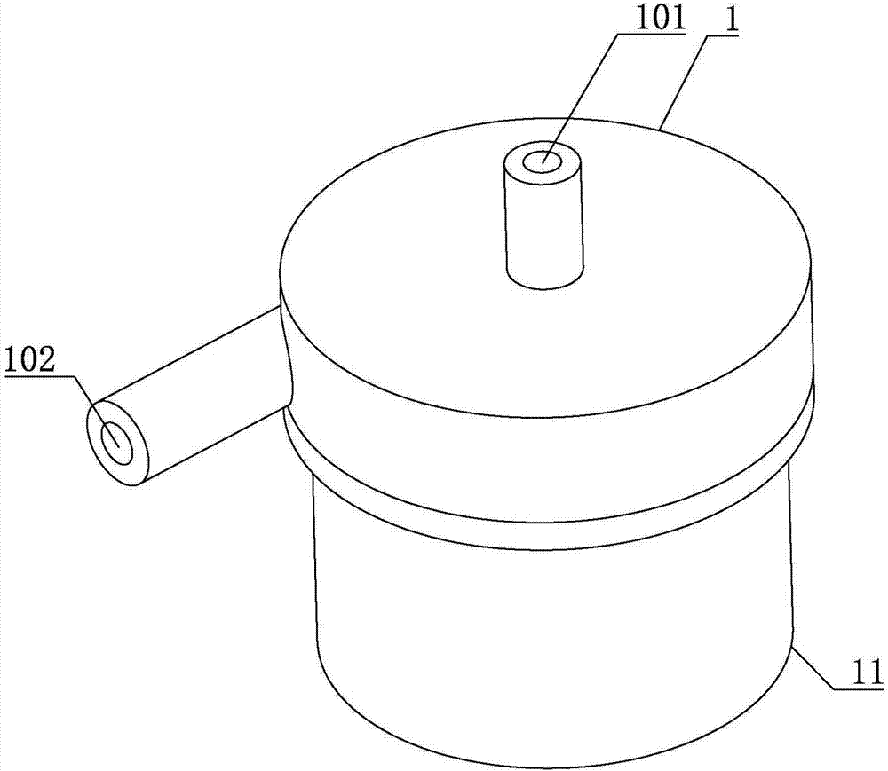
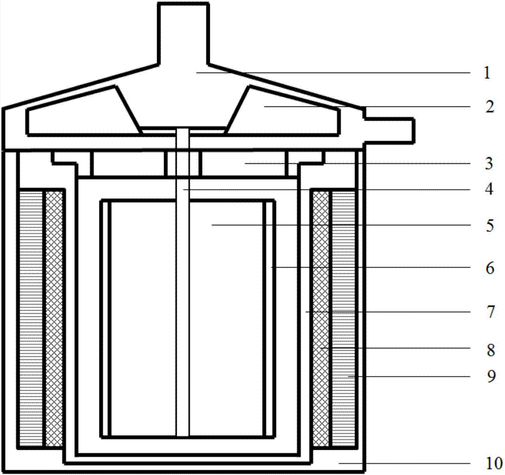
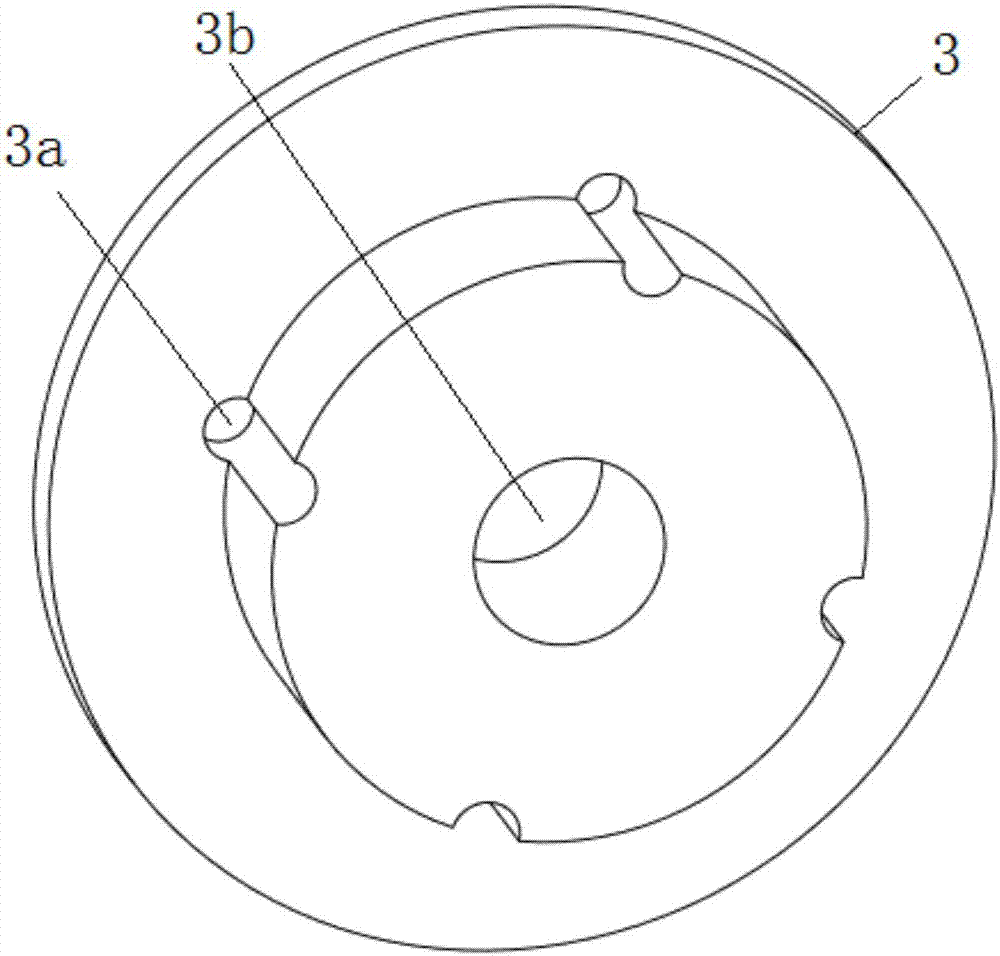
[0021] refer to Figure 1 to Figure 5 , a hydrodynamic suspension mechanical pump, comprising a volute 1, an upper end cover 3, an impeller 2, a brushless motor and a waterproof sleeve 7, wherein,

[0022] The volute 1 is provided with a water inlet channel and a water outlet channel, and the inner space of the volute 1 is used as a pump chamber, and the water inlet channel and the water outlet...


PUM


Abstract

The invention belongs to the field of minitype mechanical pumps and discloses a liquid dynamic pressure suspension mechanical pump which comprises a volute, an impeller, an upper end cover, a brushless electric machine and a waterproof sleeve, wherein the brushless electric machine comprises an electric machine shell, a silicon steel sheet, a coil, a magnetic steel rotor, a waterproof sleeve, a rotor sleeve and a rotor rotary shaft; and when the liquid dynamic pressure suspension mechanical pump works, a radial liquid dynamic pressure bearing can be formed between the outer wall of the rotor sleeve and the inner wall of the waterproof sleeve through liquid and the radial displacement of the magnetic steel rotor can be limited. As the magnetic steel rotor has magnetism, magnetic force is generated between the silicon steel sheet and the magnetic steel rotor, and the magnetic steel rotor moves in the axial direction now. In addition, when liquid enters a gap at the upper part of the magnetic steel rotor, liquid generates upward thrust to the magnetic steel rotor, and resultant force of thrust in two directions and the magnetic force can limit the axial displacement of the magnetic steel rotor, so that non-contact suspension of the magnetic steel rotor can be realized.

Description

technical field [0001] The invention belongs to the field of miniature centrifugal pumps, and more specifically relates to a mechanical pump. Background technique [0002] Since the 1980s, micro-electromechanical systems (MEMS) based on micro-processing technology have gradually entered the industrial application period from the laboratory exploration stage. Microfluidic system is a main research direction in microelectromechanical systems. It has the characteristics of small size, automation, integration and mass production, and because of its small size, it can reduce the invalid volume in the flow system, improve control accuracy, and reduce Low energy consumption and reagent consumption, and fast mechanical response. Therefore, in recent years, it has a huge market application prospect in the fields of fluid precision control, chemical analysis (such as micro-total analysis system), chip cooling and micro-satellite. As the power source in the microfluidic system, the m...

Claims


Application Information

Patent Timeline
Patent Type & Authority Applications(China)
IPC IPC(8): F04D29/047F04D13/06
CPCF04D13/06F04D29/0473
Inventor 罗小兵刘发龙段斌吴晗吴瑞康余兴建胡锦炎
Owner HUAZHONG UNIV OF SCI & TECH
Why Eureka
Try Eureka