Installation structure of the ignition coil

A technology of ignition coil and installation structure, which is applied in engine ignition, spark ignition controller, induction energy storage device, etc., can solve the problems of high precision requirements for processing and installation, breakage of spark plug ceramic body, and application of large stress, etc. Achieve the effect of avoiding breakage, improving reliability and reducing stress

Active Publication Date: 2020-01-10
CHERY AUTOMOBILE CO LTD
View PDF9 Cites 0 Cited by
  • Summary
  • Abstract
  • Description
  • Claims
  • Application Information

AI Technical Summary

Problems solved by technology

In this design state, the connection between the metal sleeve and the spark plug screw is very tight, but the position of the valve chamber cover hole, the position of the spark plug installation hole, the position of the spark plug screw, the metal sleeve of the ignition coil, and the valve chamber cover The consistency of the assembly with the cylinder head is very high. If the cumulative installation accuracy is poor, the ignition coil will exert a lot of stress on the ceramic body of the spark plug, which will easily cause the ceramic body of the spark plug to break. This is also a common failure mode
At the same time, the cost of materials such as metal sleeves and circlips added inside the ignition coil is relatively high, and the requirements for processing and installation accuracy are also high.
It can be seen that this is not a good solution

Method used


Image

  • Installation structure of the ignition coil
  • Installation structure of the ignition coil
  • Installation structure of the ignition coil

Examples


Embodiment Construction

[0015] The specific implementation manner of the present invention will be further described in detail below by describing the embodiments in conjunction with the accompanying drawings.

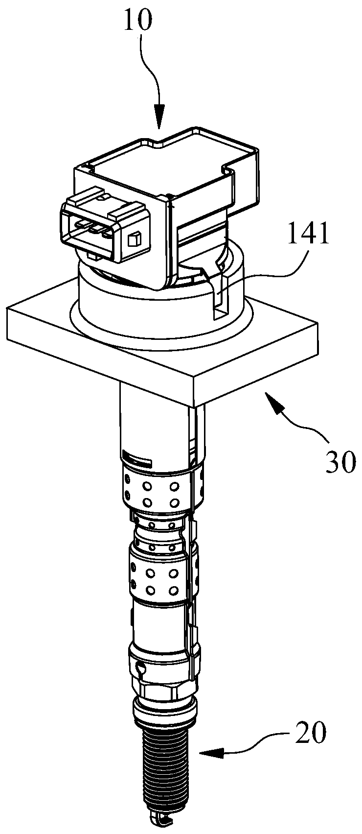
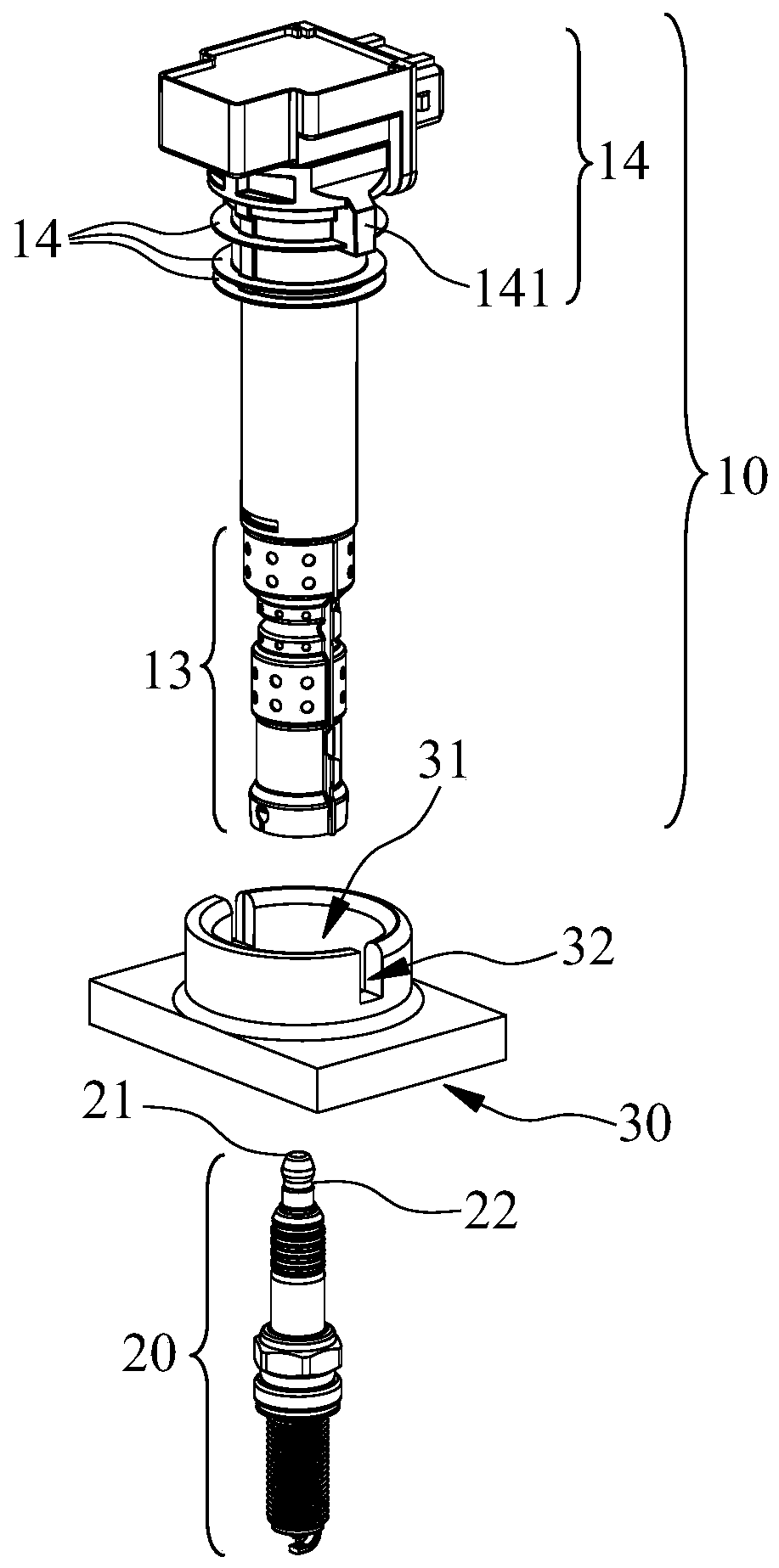
[0016] An installation structure of an ignition coil, comprising an ignition coil body 10, a contact spring 11 is connected to the high voltage end of the ignition coil body 10, a rubber sleeve 12 and an outer sheath 13 are arranged on the outside of the contact spring 11 in turn, and the high voltage core 21 of the spark plug 20 extends The rubber sleeve 12 is connected to the rubber sleeve 12 , and the rubber sleeve 12 is provided with a limiting unit, which prevents the spark plug 20 from axially shifting in the rubber sleeve 12 . The high-voltage core 21 of the spark plug 20 extends into the rubber sleeve 12 and cooperates with the limit unit, which not only limits the radial displacement of the spark plug 20 in the rubber sleeve 12, but also limits its axial displacement, ensuring that th...


PUM


Abstract

The invention belongs to the technical field of ignition systems of automobile engines, and particularly relates to a mounting structure of an ignition coil. The mounting structure of the ignition coil comprises an ignition coil body, a high voltage end of the ignition coil body is connected with a contact spring, a rubber sleeve and an outer protective sleeve are sequentially arranged on the outer portion of the contact spring in a defining mode, a high voltage core of an ignition plug extends into the rubber sleeve and is connected with the rubber sleeve, a limiting unit is arranged in the rubber sleeve, and the limiting unit prevents the ignition plug from conducting axial displacement in the rubber sleeve. According to the mounting structure of the ignition coil, the high voltage core of the ignition plug extends into the rubber sleeve and is matched with the limiting unit, reliable connection of the ignition coil and the ignition plug is ensured, the rubber sleeve has certain elasticity so that stress applied by the ignition coil on an ignition plug ceramic body can be reduced greatly, therefore the problem of breaking off of the ignition plug ceramic body is avoided, and accordingly the reliability of assembly of the ignition coil is improved.

Description

technical field [0001] The invention belongs to the technical field of ignition systems of automobile engines, and in particular relates to an installation structure of ignition coils. Background technique [0002] At present, there are two main installation and fixation schemes for ignition coils of automobile engines: [0003] One is to fix the ignition coil on the valve chamber cover by bolts. This installation method is relatively reliable, but this connection method requires an additional boss for the inlay on the ignition coil. On the valve chamber cover A corresponding boss or threaded hole insert for arranging the installation holes needs to be provided, which undoubtedly increases the arrangement space, increases the weight and production cost of the ignition system. Under the trend of gradually reducing the size and weight of the engine, the bolt-on solution will gradually fail to meet the requirements. [0004] The other is to make a metal sleeve inside the igni...

Claims


Application Information

Patent Timeline
Patent Type & Authority Patents(China)
IPC IPC(8): F02P15/00F02P3/04
CPCF02P3/04F02P15/00
Inventor 徐茂生俞京
Owner CHERY AUTOMOBILE CO LTD
Why Eureka
Try Eureka