Simple and convenient thin metal sheet drilling machine device

A metal plate and hole processing technology, which is applied to metal processing equipment, feeding devices, positioning devices, etc., can solve the problems of high price, slow drilling speed, low drilling quality, etc., and achieves low manufacturing cost and maintenance cost. Fast punching speed and good punching quality

Inactive Publication Date: 2017-07-28
衢州市洼帝尔数控设备有限公司
View PDF10 Cites 78 Cited by
  • Summary
  • Abstract
  • Description
  • Claims
  • Application Information

AI Technical Summary

Problems solved by technology

[0002] At present, the methods used for punching thin plates in the production process are mainly the following: the thin metal plate is punched by manually drawing a circle and then holding a drill bit punching equipment. The speed is slow, which affects the production process of the entire workpiece. In addition, it is easy to cause burrs after drilling, and the quality of

Method used


Image

  • Simple and convenient thin metal sheet drilling machine device
  • Simple and convenient thin metal sheet drilling machine device
  • Simple and convenient thin metal sheet drilling machine device

Examples


Embodiment Construction

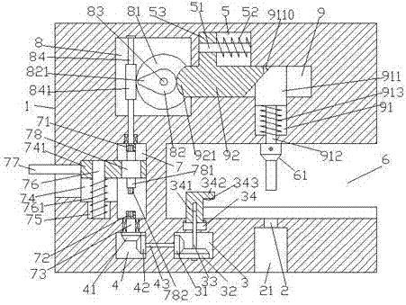
[0024] Such as Figure 1-Figure 6 As shown, a simple thin metal plate punching processing device of the present invention includes a body 1, an operation groove 6 is arranged in the right end surface of the body 1, and an operation groove 6 is arranged in the left side of the body 1 of the operation groove 6. A switching chamber 7 is provided, the upper and lower inner walls of the switching chamber 7 are respectively provided with a first inner spline shaft 71 and a second inner spline shaft 72, and the left inner wall of the switching chamber 7 is provided with a first sliding groove 74 , the inner bottom wall of the first sliding groove 74 is provided with a sinking groove 75, and a first guide rod 76 is arranged between the inner bottom wall of the sinking groove 75 and the inner top wall of the first sliding groove 74. A first sliding block 741 extending to the right is connected to the guide rod 76 by sliding fit. The outer surface of the first guide rod 76 at the bottom...


PUM


Abstract

The invention discloses a simple and convenient thin metal sheet drilling machine device. The device comprises a device body. An operating groove is formed in the end face of the right side of the device body. A switching cavity is formed in the portion, on the left side of the operating groove, of the device body. A first inner spline shaft and a second inner spline shaft are arranged on the inner walls of the upper side and the lower side of the switching cavity correspondingly. A first sliding groove is formed in the inner wall of the left side of the switching cavity. A sediment groove is formed in the inner bottom wall of the first sliding groove. A first guide rod is arranged between the inner bottom wall of the sediment groove and the inner top wall of the first sliding groove. A first sliding block extending rightwards is slidably connected to the first guide rod in a matched mode. A first spring is arranged on the outer surface of the first guide rod located at the bottom of the first sliding block in a surrounding mode. A right extending section of the first sliding block extends into the switching cavity and abuts against the inner wall of the right side of the switching cavity in a sliding fit mode. A motor is arranged in the first sliding block in the switching cavity. Driving shafts are arranged at the ends of the upper side and the lower side of the motor. A transmission cavity is formed in the portion, above the switching cavity, in the device body. The device is simple in structure, convenient to operate, low in manufacturing and maintaining cost, high in drilling speed and stability and good in drilling quality.

Description

technical field [0001] The invention relates to the technical field of punching, in particular to a simple punching device for thin metal plates. Background technique [0002] At present, the methods used for punching thin plates in the production process are mainly the following: the thin metal plate is punched by manually drawing a circle and then holding a drill bit punching equipment. The speed is slow, which affects the production process of the entire workpiece. In addition, it is easy to cause burrs after drilling, and the quality of the drilling is low; drilling through hydraulic drilling equipment is slow, expensive, and heavy and difficult to carry. In addition, due to When the traditional thin plate is fixed and punched, the smooth surface is easy to cause the punching deviation when punching, resulting in a low pass rate, and the locking operation is cumbersome and affects the overall production speed. Contents of the invention [0003] The technical problem t...

Claims


Application Information

Patent Timeline
IPC IPC(8): B21D28/26B21D43/00
CPCB21D28/265B21D43/003
Inventor 吴俊
Owner 衢州市洼帝尔数控设备有限公司
Why Eureka
Try Eureka