High-voltage relay
A high-voltage relay, highly advanced technology, applied in the direction of relays, electromagnetic relays, detailed information of electromagnetic relays, etc., can solve the problems of reducing the service life of the return force spring, melting and damage of the return force spring, poor reliability of the relay, etc., to extend the service life, Improve reliability and avoid stuck effects
- Summary
- Abstract
- Description
- Claims
- Application Information
AI Technical Summary
Problems solved by technology
Method used
Image

Examples
Embodiment 1
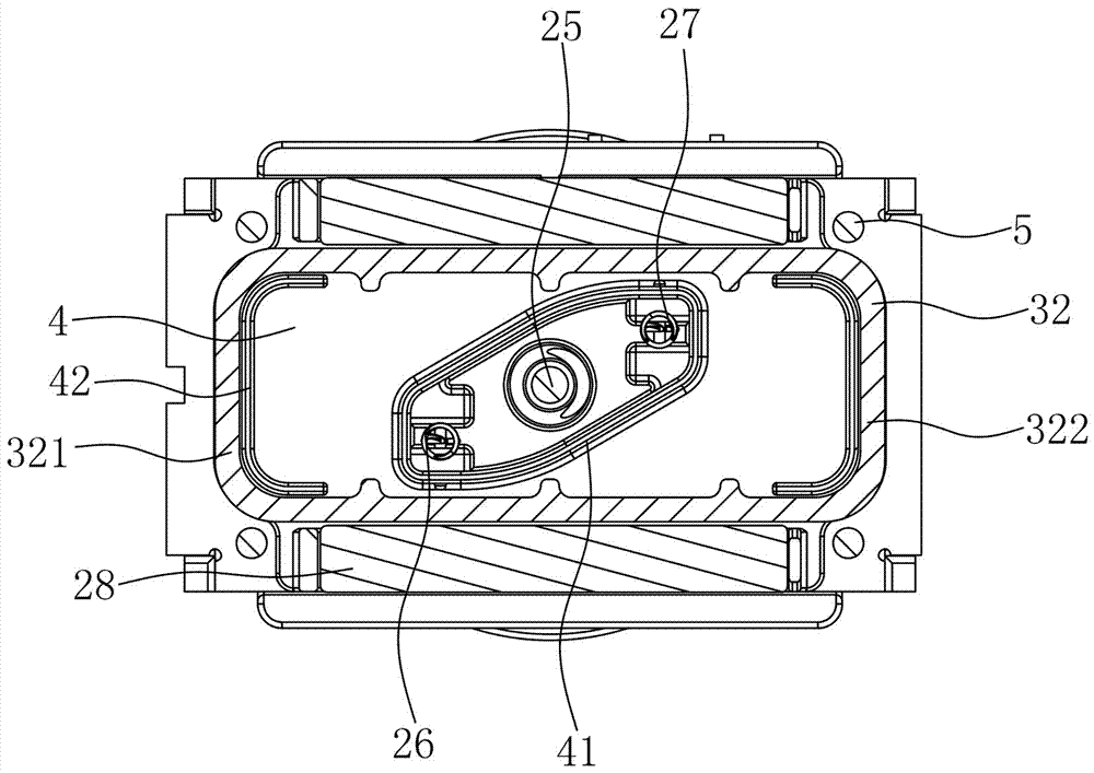
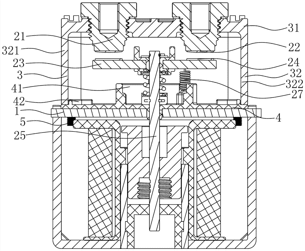
[0031] Depend on figure 1 , figure 2 As shown, a high-voltage relay of the present invention includes a yoke 1, a static contact assembly and a moving contact assembly arranged above the yoke 1, the static contact assembly includes a lead-out 21 and a static contact 22, and the moving contact The assembly includes a moving reed 23 and a moving contact 24, the moving reed 23 is fixed to the upper end of the push rod 25, the lower end of the push rod 25 is located below the yoke 1, and the upper side of the yoke 1 is provided with an insulating cover made of ceramic material sintered 3 and a positioning plate 4 of plastic material, the insulating cover 3 cooperates with the yoke 1 to form a chamber for accommodating the movable contact assembly and the static contact assembly, the insulating cover 3 includes a top plate 31 and an enclosure 32, the top plate 31 is used In order to fix the static contact assembly, the positioning plate 4 is formed with a positioning plate throug...
Embodiment 2
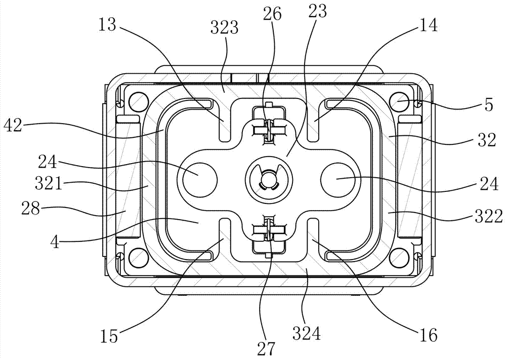
[0036] Depend on image 3 , Figure 4 As shown, a high-voltage relay of the present invention includes a yoke 1, a static contact assembly and a moving contact assembly arranged above the yoke 1, the static contact assembly includes a lead-out 21 and a static contact 22, and the moving contact The assembly includes a moving reed 23 and a moving contact 24, the moving reed 23 is fixed to the upper end of the push rod 25, the lower end of the push rod 25 is located below the yoke 1, and the upper side of the yoke 1 is provided with an insulating cover made of ceramic material sintered 3 and a positioning plate 4 made of plastic, the insulating cover 3 is fixed with the yoke 1 to form a chamber for accommodating the movable contact assembly and the static contact assembly, the insulating cover 3 includes a top plate 31 and an enclosure 32, the top plate 31 is used to fix the static contact assembly. The positioning plate 4 is formed with a positioning plate through hole that pen...
Embodiment 3
[0040] Depend on Figure 5 , Image 6 , Figure 7 As shown, a high-voltage relay of the present invention includes a yoke 1, a static contact assembly and a moving contact assembly arranged above the yoke 1, the static contact assembly includes a lead-out 21 and a static contact 22, and the moving contact The assembly includes a moving reed 23 and a moving contact 24, the moving reed 23 is fixed to the upper end of the push rod 25, the lower end of the push rod 25 is located below the yoke 1, and the upper side of the yoke 1 is provided with an insulating cover made of ceramic material sintered 3 and a positioning plate 4 made of plastic, the insulating cover 3 is fixed with the yoke 1 to form a chamber for accommodating the movable contact assembly and the static contact assembly, the insulating cover 3 includes a top plate 31 and an enclosure 32, the top plate 31 is used to fix the static contact assembly. The positioning plate 4 is formed with a positioning plate through ...
PUM
 Abstract
Description
Claims
Application Information
 - R&D
- Intellectual Property
- Life Sciences
- Materials
- Tech Scout
- Unparalleled Data Quality
- Higher Quality Content
- 60% Fewer Hallucinations
Browse by: Latest US Patents, China's latest patents, Technical Efficacy Thesaurus, Application Domain, Technology Topic, Popular Technical Reports.
© 2025 PatSnap. All rights reserved.Legal|Privacy policy|Modern Slavery Act Transparency Statement|Sitemap|About US| Contact US: help@patsnap.com