
Temporary illumination lamp for workshop

A lighting lamp, a temporary technology, applied in lighting devices, lighting and heating equipment, components of lighting devices, etc., can solve the problems of short service life of lamp caps, electric shock accidents of electric sockets, easy disassembly and assembly of lighting lamps, etc., and achieves convenient operation. , Protect the safety of electricity consumption, and ensure the effect of stable power supply

Inactive Publication Date: 2017-07-25
广州常佰机械设计有限公司
View PDF7 Cites 2 Cited by
  • Summary
  • Abstract
  • Description
  • Claims
  • Application Information

AI Technical Summary

Problems solved by technology

[0002] The mechanical production workshop should set up temporary lights for partial lighting for production needs. The workshop operation requires that the temporary lights use high-power lamp holders as much as possible to ensure good lighting conditions, and the high-power lamp holders have a shorter service life and are easier Damaged, often need to be replaced, which requires easy disassembly and assembly of temporary lighting; and the electric base of traditional temporary lighting is prone to electric shock accidents, there is a need to strengthen safety

Method used


Image

  • Temporary illumination lamp for workshop
  • Temporary illumination lamp for workshop
  • Temporary illumination lamp for workshop

Examples


Embodiment Construction

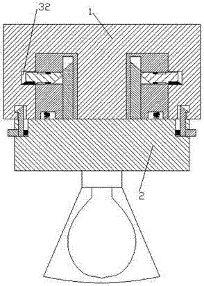
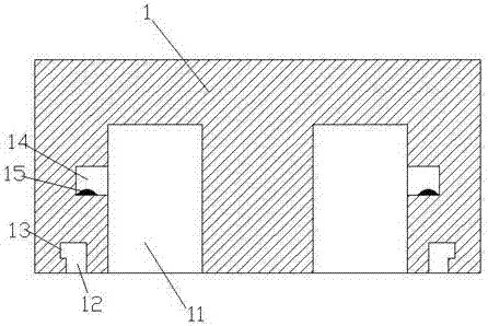
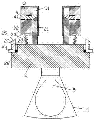
[0017] Combine below Figure 1-5 The present invention will be described in detail.

[0018] refer to Figure 1-5 According to an embodiment of the present invention, a temporary lighting lamp for a workshop includes an electric base 1 and a lighting device 2 fixedly mounted on a mobile frame. Both sides are provided with energizing parts 14, and the front part of the energizing part 14 is provided with a energizing copper sheet 15, and the front part of the electric seat 1 is symmetrically provided with locking through grooves 12, and the rear part of the locking through grooves is arranged There is a locking part 13 extending outward, and the locking through groove 12 is located outside the insertion groove 11; the rear surface of the lighting device 2 is symmetrically provided with an electric plug-in, and the electric plug-in includes a The slot 11 fits the insert block 3 and the movable rod 21 fixedly arranged on the rear surface of the lighting device 2, the insert blo...


PUM


Abstract

The invention discloses a temporary illumination lamp for a workshop. The temporary illumination lamp comprises an electric base and an illumination device, wherein the electric base and the illumination device are fixedly installed on a moving frame. Insertion grooves are symmetrically formed in the left side and the right side of the electric base, and electrifying parts are arranged on the two sides of the insertion grooves. Electrifying copper sheets are arranged in the front portions of the electrifying parts. Locking through grooves are symmetrically formed in the left side and the right side of the front portion of the electric base. The rear portions of the locking through grooves are provided with locking parts extending outwards. Electrifying insertion pieces are symmetrically arranged on the left side and the right side of the rear portion face of the illumination part. Each electrifying insertion piece comprises an insertion block matched with the corresponding insertion groove and a movable rod fixedly arranged on the rear portion face of the illumination device. A vertical groove and a transverse groove are formed in each insertion block, wherein the transverse groove communicates with the vertical groove. The movable rods stretch in the vertical grooves, movable arms are movably installed in the transverse grooves, and sliding guide parts and acting parts are arranged on the inner side portions of the movable arms. The sliding guide parts move out of the transverse grooves, stretch in the vertical grooves and interact with the acting parts at the rear portions of the movable rods.

Description

technical field [0001] The invention relates to the field of mechanical production, in particular to a temporary lighting lamp for a workshop. Background technique [0002] The mechanical production workshop should set up temporary lights for partial lighting for production needs. The workshop operation requires that the temporary lights use high-power lamp holders as much as possible to ensure good lighting conditions, and the high-power lamp holders have a shorter service life and are easier If damaged, they often need to be replaced, which requires that the temporary lighting lamps are easy to disassemble; and the electric sockets of traditional temporary lighting lamps are prone to electric shock accidents, so there is a need to enhance safety. Contents of the invention [0003] The object of the present invention is to provide a workshop temporary lighting lamp, which is used to overcome the above-mentioned defects in the prior art. [0004] A temporary lighting lamp...

Claims


Application Information

Patent Timeline
Patent Type & Authority Applications(China)
IPC IPC(8): F21V19/00F21V23/06F21V7/22
CPCF21V19/00F21V7/22F21V23/06
Inventor 时建华
Owner 广州常佰机械设计有限公司
Learn More