
Emergency oil supply system for steam turbine generator set

A technology for generating sets and oil supply systems, which is applied in the field of lubricating oil systems, and can solve the problems that AC lubricating oil pumps and DC lubricating oil pumps cannot be started, are difficult to implement, and economic losses of power generation companies.

Inactive Publication Date: 2017-07-25
河北建投能源科学技术研究院有限公司
View PDF4 Cites 0 Cited by
  • Summary
  • Abstract
  • Description
  • Claims
  • Application Information

AI Technical Summary

Problems solved by technology

[0004] Twenty-five countermeasures are an important criterion for power generation companies. However, in recent years, many units have experienced failures in the safety section and DC section due to power failure, or simultaneous failure of the AC lubricating oil pump and the DC lubricating oil pump. Neither the pump nor the DC lubricating oil pump can be started, resulting in a vicious accident in which the unit cuts off the oil and burns the tiles, causing huge economic losses to the power generation company
[0005] Chinese patent 201620671351X discloses a steam turbine lubricating oil system that prevents oil-cutting and burning of tiles. A high-level oil tank is arranged above the main oil tank; The height of the fuel tank needs to be set nearly 10m higher than the center line of the unit, and the volume of the high-level fuel tank is many times larger than that of the main fuel tank. Therefore, the construction of a high-level fuel tank has higher requirements for the building of the machine room, and the one-time investment is large, and the maintenance cost is high; especially It is almost difficult to implement the units that have been put into operation and need to change the original building structure

Method used


Image

  • Emergency oil supply system for steam turbine generator set

Examples


Embodiment Construction

[0016] The present invention will be further described in detail below in conjunction with the accompanying drawings and specific embodiments.

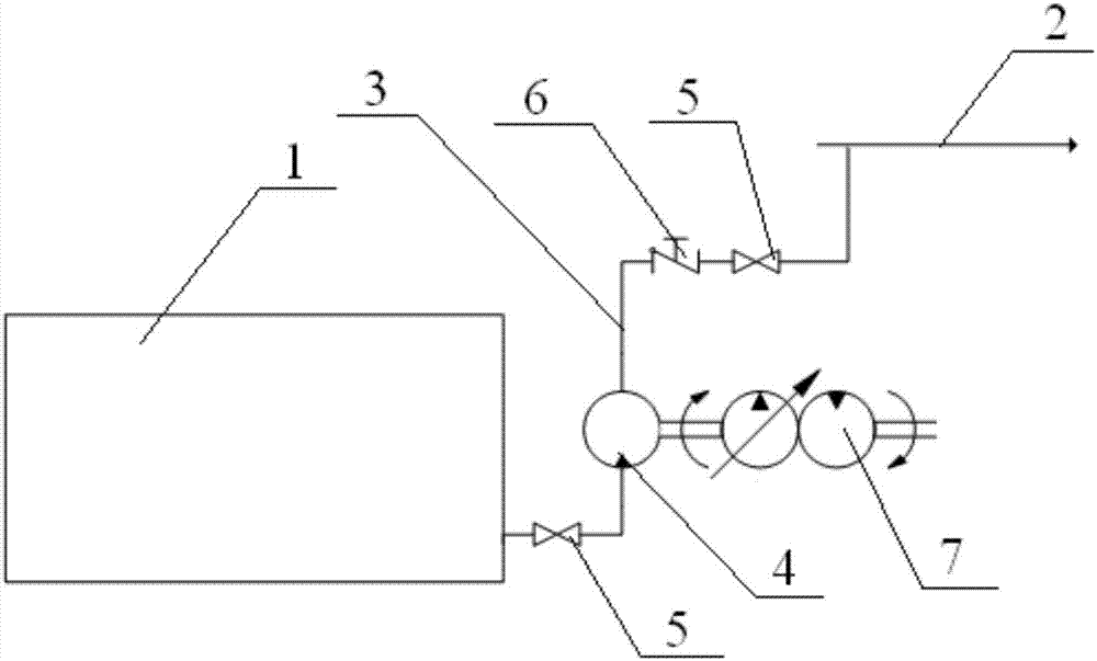
[0017] An emergency oil supply system for a steam turbine generating set, the structure of which is as follows figure 1 As shown, it includes a centrifugal pump 4, a diesel engine 7, a check valve 6, an oil pipeline 3 and two manual valves 5, the oil pipeline 3 is used to connect the main oil tank 1 and the lubricating oil main pipe 2, and the centrifugal pump 4 is arranged on the oil pipeline 3 Among them, the drive shaft of the centrifugal pump is connected to the output shaft of the diesel engine, and the diesel engine drives the centrifugal pump to work; the check valve 6 is arranged in the oil pipeline between the centrifugal pump 4 and the lubricating oil main pipe 2 to prevent the lubricating oil from flowing backward; two manual The valves are respectively arranged in the oil pipelines at both ends of the centrifugal pump 4, a...


PUM


Abstract

The invention discloses an emergency oil supply system for a steam turbine generator set. The system comprises a centrifugal pump arranged between a main oil tank and a lubricating oil mother pipe through an oil pipeline, and the centrifugal pump is driven by a diesel engine connected with the centrifugal pump; a check valve preventing lubricating oil from flowing reversely is arranged in the portion, between the centrifugal pump and the lubricating oil mother pipe, of the oil pipeline; manual valves are arranged in the portions, located at the two ends of the centrifugal pump, of the oil pipeline respectively. The emergency oil supply system is applied to the steam turbine generator set to serve as a spare oil supply system, can supply lubricating oil to the steam turbine generator set when an alternating-current lubricating oil pump and a direct-current lubricating oil pump both cannot be started, it is guaranteed that the set can be stopped smoothly, vicious accidents of bearing burnout due to oil breakoff and shaft grinding are avoided, and a reliable guarantee is provided for the safety of the set.

Description

technical field [0001] The invention relates to the technical field of steam turbine generator sets in thermal power plants, in particular to a lubricating oil system for steam turbine generator sets. Background technique [0002] The steam turbine lubricating oil system is mainly used to provide lubricating oil to the bearings of the steam turbine generator set, and at the same time provide working oil to the crisis blocking device, generator sealing oil device and jacking oil system. The traditional steam turbine lubricating oil system consists of a main oil pump, an AC lubricating oil pump and a DC lubricating oil pump. The AC lubricating oil pump mainly supplies lubricating oil to the system when the unit starts and stops, and the main oil pump supplies lubricating oil to the system during normal operation. The DC lubricating oil pump is an emergency lubricating oil pump. [0003] According to the "8.4 Prevention of Steam Turbine and Gas Turbine Bearing Damage Accidents...

Claims


Application Information

Patent Timeline
IPC IPC(8): F01D25/20
CPCF01D25/20
Inventor 曹伟牟法海王彦海王博磊丁宁张建华
Owner 河北建投能源科学技术研究院有限公司
Learn More