
Efficient flame retardant device

A fire-blocking and efficient technology, applied in the pipeline system, gas/liquid distribution and storage, mechanical equipment, etc., can solve the problems of cutting off the gas source, difficult to detect, etc., to avoid back channeling, improve sensitivity, and ensure safety.

Pending Publication Date: 2017-07-21
广东蓝新氢能源科技有限公司
View PDF16 Cites 1 Cited by
  • Summary
  • Abstract
  • Description
  • Claims
  • Application Information

AI Technical Summary

Problems solved by technology

Refer to the public document: A multi-stage stacked variable-diameter split flow anti-reflash tank device, publication number: CN106051466A, publication date: 2016-10-26, using multiple tanks filled with water in series to achieve fire resistance Purpose, but when the hydrogen fuel is backfired, the pressure increases rapidly, and the hydrogen molecules will generate a large number of free radicals to return to the direction of the gas source. The free radicals collide with other molecules to form new products and new free radicals. The radicals continue to react with other molecules, and the free radicals have the opportunity to pass through the tank through the gas channel in the liquid. Therefore, before the tempering seedlings enter the tank containing the liquid, a large number of free radicals produced by tempering must be removed. At the same time, for the sake of safety, an inspection device must be installed in the front of the high-efficiency fire arresting device, but because the number of free radicals is not large, it is difficult to detect, so it is difficult to cut off the gas source when the tempering just occurs

Method used


Image

  • Efficient flame retardant device
  • Efficient flame retardant device
  • Efficient flame retardant device

Examples


Embodiment Construction

[0016] In the following, the present invention will be further described in conjunction with the accompanying drawings and specific embodiments, so as to understand more clearly the technical idea claimed in the present invention.

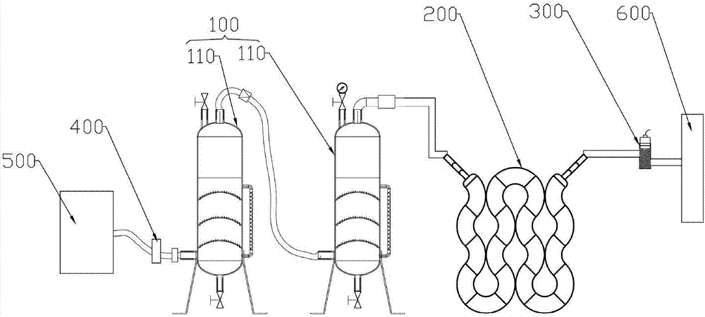
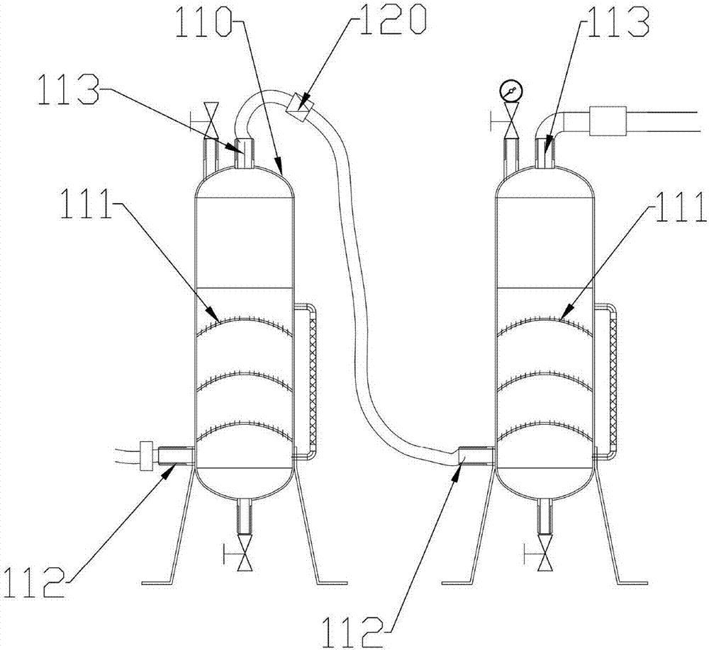
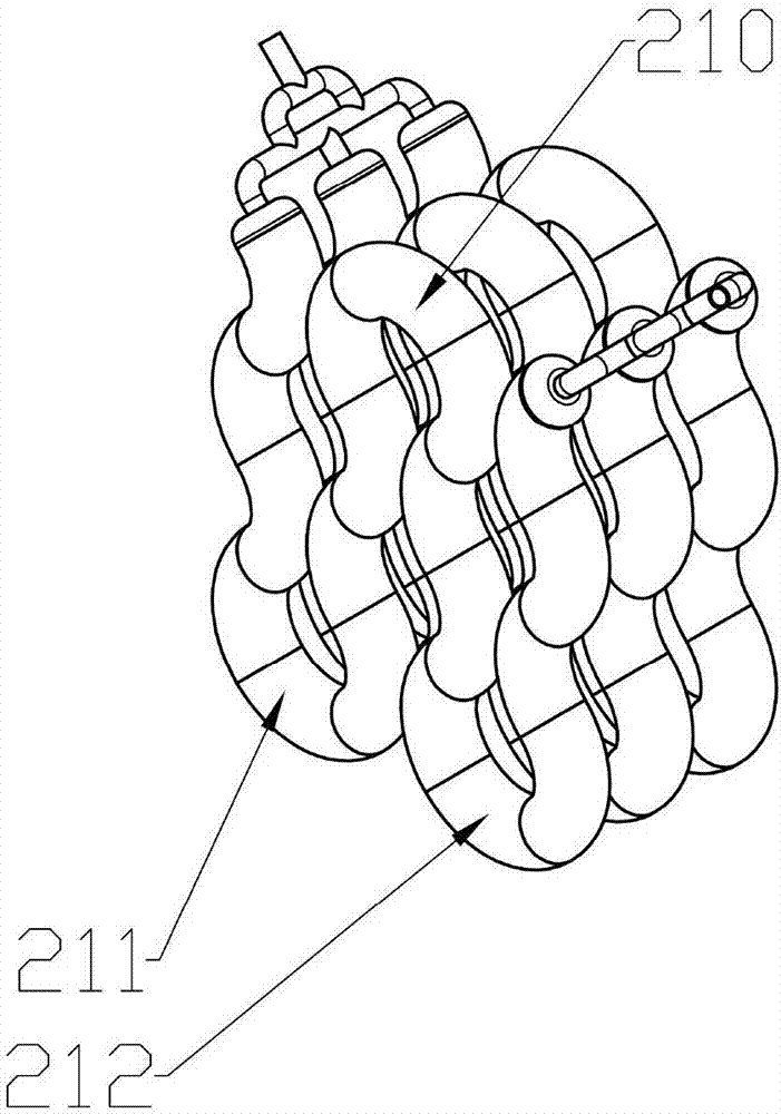
[0017] refer to figure 1 , a high-efficiency fire arresting device, the high-efficiency fire arresting device is installed between the gas supply end 500 and the use end 600, the gas supply end 500 supplies hydrogen-oxygen mixed gas, from the gas supply end 500 to the use end 600, the high-efficiency fire arresting device sequentially includes an electronic check valve 400, a water-type fire arresting mechanism 100, a dry-type fire arresting mechanism 200, and the free radical detection device 300, and the free radical detection device 300 is connected to the The electronic check valves 400 are respectively electrically connected to the controller, and the controller controls the opening and closing of the electronic check valves 400 according to t...


PUM


Abstract

The invention provides an efficient flame retardant device. The efficient flame retardant device is installed between a gas supply end and a client side, and sequentially comprises an electronic check valve, a water type flame retardant mechanism, a dry type flame retardant mechanism and a free radical detection device in the direction from the gas supply end to the client side, and the free radical detection device and the electronic check valve are electrically connected with a controller. According to the efficient flame retardant device, the water type flame retardant mechanism and the dry type flame retardant mechanism are connected in series, lots of free radicals in tempering flames can be eliminated through the dry type flame retardant mechanism, then, cooling is conducted through the water type flame retardant mechanism, and thus, shifting of the tempering flames can be thoroughly avoided; moreover, the front end of the efficient flame retardant device is additionally provided with the free radical detection device which adopts a mode that signals of the free radicals are amplified through copper wires, and then detecting is conducted, and accordingly, the sensitivity of the free radical detection device can be improved. Through the efficient flame retardant device, the flame retardant effect can be well achieved, and the safety of the gas source end is ensured.

Description

technical field [0001] The invention relates to the technical field of fire arresting devices in hydrogen-oxygen mixed gas delivery pipelines, in particular to a high-efficiency fire arresting device. Background technique [0002] In the process of using flammable gases, high-efficiency fire arresting devices are required. High-efficiency fire arresting devices, also known as fire prevention devices, are safety devices used to prevent the flame spread of flammable gases and flammable liquid vapors, and prevent equipment from flashing back Occasionally cause potential safety hazards at the gas source end. Refer to the public document: A multi-stage stacked variable-diameter split flow anti-reflash tank device, publication number: CN106051466A, publication date: 2016-10-26, which uses multiple tanks filled with water in series to achieve fire resistance Purpose, but when the hydrogen fuel is tempered, the pressure increases rapidly, and the hydrogen molecules will generate a ...

Claims


Application Information

Patent Timeline
IPC IPC(8): F17D5/00F17D3/01
CPCF17D3/01F17D5/005
Inventor 唐以松唐立豪朱敏陈沼锟
Owner 广东蓝新氢能源科技有限公司
Learn More