Cutter for electrical adhesive tape

A technology of electrical tape and cutter, which is applied in the directions of sending objects, thin material handling, transportation and packaging, etc., can solve the problems of troublesome operation, troublesome cutting process of electrical tape, inconvenient to turn around, and inconvenient to take and place tools, so as to achieve a reasonable structure. , Easy to carry and use

Inactive Publication Date: 2017-07-21
HENAN YAAN ELECTRICAL INSULATION MATERIAL PLANT CO LTD
View PDF9 Cites 5 Cited by
  • Summary
  • Abstract
  • Description
  • Claims
  • Application Information

AI Technical Summary

Problems solved by technology

[0002] Electrical tape is an electrical insulating adhesive tape. It is made of soft polyvinyl chloride film as the base material and rubber-coated pressure-sensitive adhesive. It has good insulation, flame resistance, voltage resistance, and cold resistance. Its use effect is good and It has a wide range of applications; however, after the electrical tape is wound, it needs to use a knife to cut it, which is cumbersome to operate, especially when the electrician is working at high altitude, it is very inconvenient to turn around and take and place tools, and there is a certain danger. The process of cutting the electrical tape is particularly troublesome; and, after the existing electrical tape is used, due to its own adhesion, the joint and the tape itself are bonded together, and it is necessary to find the joint again when it is used next time, which is a waste of time and For the user's use has increased trouble; In order to solve the above problems, it is necessary to develop a kind of electrical tape cutter with reasonable structure and easy to carry and use.

Method used


Image

  • Cutter for electrical adhesive tape
  • Cutter for electrical adhesive tape
  • Cutter for electrical adhesive tape

Examples


Embodiment Construction

[0019] The technical solutions of the present invention will be further specifically described below through embodiments and in conjunction with the accompanying drawings.

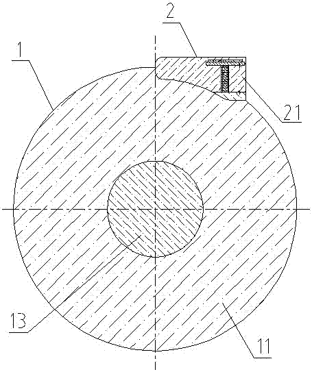
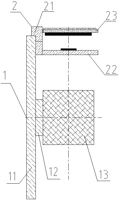
[0020] Such as figure 1 , figure 2 , image 3 , Figure 4 Shown: a cutter for electrical tapes, including a tape holder 1 and a cutting device 2, the tape holder 1 includes a baffle 11, a connecting shaft 12 and a drum 13, the baffle 11 is circular, The connecting shaft 12 is arranged at the center of the inner surface of the baffle plate 11, and is fixed and vertically connected with the baffle plate 11. The rotating cylinder 13 is a cylindrical structure with one end open, and the rotating cylinder 13 is sheathed on the baffle plate 11. The outer side of the connecting shaft 12 is rotationally connected with the connecting shaft 12; the cutting device 2 includes a fixed plate 21, a bottom plate 22 and a cutting plate 23, the fixed plate 21 is fixedly welded to the inner surface of the baffle plate 11...


PUM


Abstract

The invention discloses a cutter for electrical tape, which comprises a tape fixing frame and a cutting device. The tape fixing frame includes a baffle, a connecting shaft and a rotating drum, the connecting shaft is fixed and vertically arranged at the center of the inner surface of the baffle, and the rotating drum Sleeved on the outside of the connecting shaft and connected with the connecting shaft in rotation; the cutting device includes a fixed plate, a bottom plate and a cutting plate, the fixed plate and the inner surface of the baffle are fixedly welded, the bottom plate and the fixed plate are vertically fixedly connected, and the upper surface of the bottom plate is provided with a bump and the cutting groove, the protrusion is located inside the cutting groove, a slide bar is arranged inside the fixed plate, and a spring is set on the outer end of the slide bar, and the cutting plate is connected with the slide bar through a buckle fixed on its side end, and the buckle is set on the slide The outer end of the rod and the lower surface of the cutting plate are fixed with a cutter matching the cutting groove structure, and the inner side of the cutter is provided with a through groove matching the bump structure; the present invention has the advantages of reasonable structure and convenient portability and use.

Description

technical field [0001] The invention belongs to the technical field of cutting tools, and in particular relates to a cutter for electrical tapes. Background technique [0002] Electrical tape is electrical insulating adhesive tape, which is made of soft polyvinyl chloride film as the base material and rubber-coated pressure-sensitive adhesive. It has good insulation, flame resistance, voltage resistance, cold resistance and other characteristics. Its use effect is good and It has a wide range of applications; however, after the electrical tape is wound, it needs to use a knife to cut it. The operation is cumbersome, especially when the electrician is working at a high altitude. The process of cutting the electrical tape is particularly troublesome; and, after the existing electrical tape is used, due to its own adhesion, the joint and the tape itself are bonded together, and the next time it is used, it is necessary to find the joint again, which is a waste of time and It i...

Claims


Application Information

Patent Timeline
Patent Type & Authority Applications(China)
IPC IPC(8): B65H35/07
CPCB65H35/0026B65H35/0073B65H35/008
Inventor 慕洪王建伟
Owner HENAN YAAN ELECTRICAL INSULATION MATERIAL PLANT CO LTD
Why Eureka
Try Eureka