Permanent magnetism motor rotor and motor

A permanent magnet motor and rotor technology, applied in the direction of magnetic circuit rotating parts, magnetic circuits, electrical components, etc., can solve the problem that the supporting force cannot resist centrifugal force, etc., to ensure the strength, solve the magnetic leakage, and improve the utilization rate.

Active Publication Date: 2017-07-18
李致真
View PDF6 Cites 7 Cited by
  • Summary
  • Abstract
  • Description
  • Claims
  • Application Information

AI Technical Summary

Problems solved by technology

[0003] The rotor of a permanent magnet motor is composed of a rotating shaft, a rotor core, a permanent magnet and additional supports. The rotor core is made of stacked punching sheets, and magnetic steel slots are evenly distributed on the punching sheets around the center of the rotating shaft, and the permanent magnets are embedded. Placed in the magnetic steel groove, there will be magnetic flux leakage at both ends of the permanent magnet. In order to limit the amount of magnetic flux leakage, the general measure is to narrow the magnetic flux leakage bridge on the side of the magnetic steel groove towards the air gap as much as possible, and place a bridge between the two poles of the permanent magnet. The air magnetic isolation slots are set up, but the magnetic flux leakage bridges need to be reserved between the air magnetic isolation slots, and the magnetic flux leakage bridges should not be too narrow, otherwise the supporting force of the punching piece to the permanent magnet will not be enough to resist the centrifugal force under high-speed rotation

Method used


Image

  • Permanent magnetism motor rotor and motor
  • Permanent magnetism motor rotor and motor
  • Permanent magnetism motor rotor and motor

Examples


Embodiment 1

[0021] Embodiment one: see Figure 1 to Figure 3 :

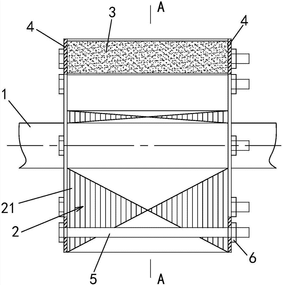
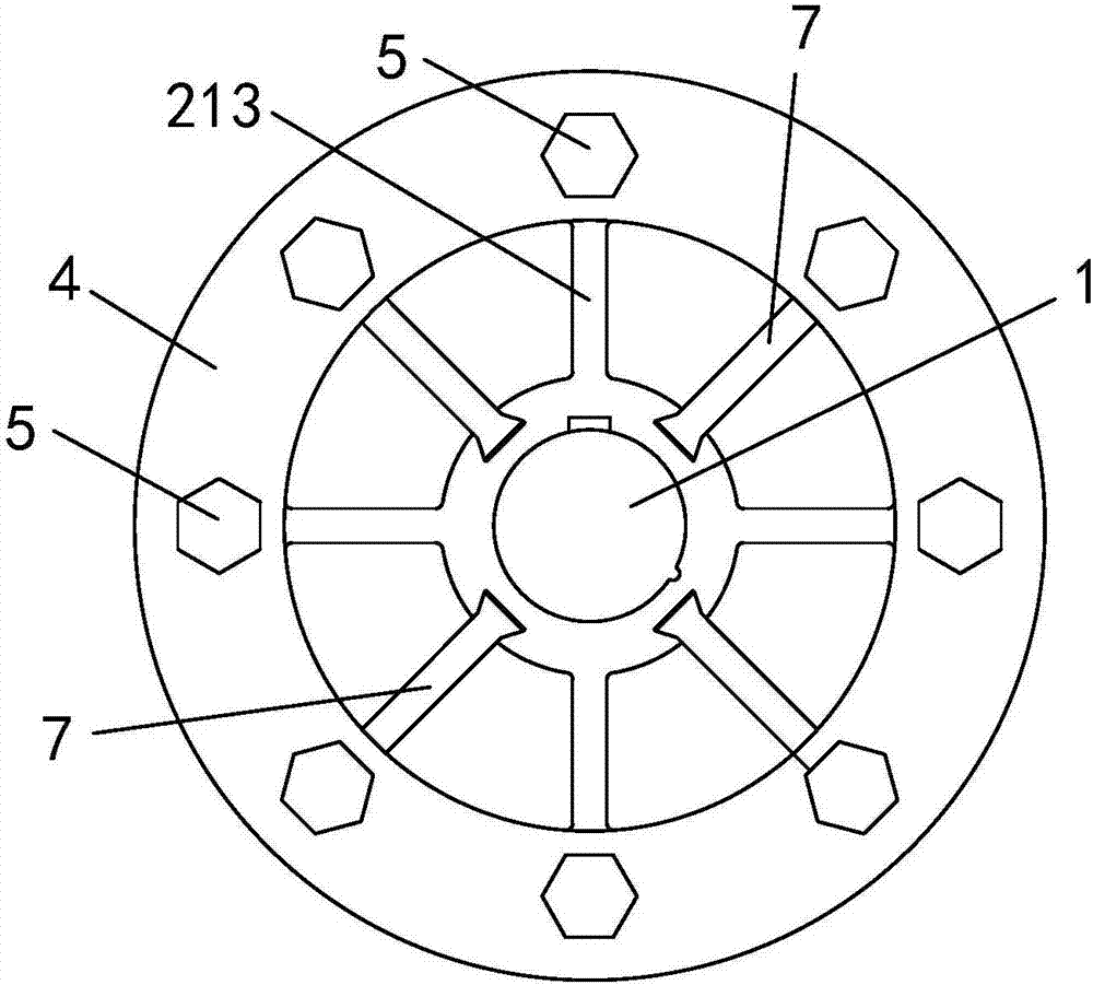
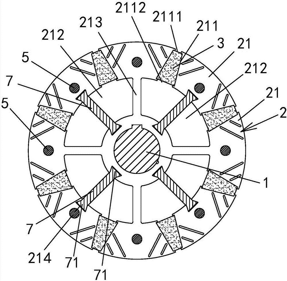
[0022] A permanent magnet motor rotor, including a rotating shaft 1, a rotor core 2 and a permanent magnet 3, the rotor core 2 is stacked by punching sheets 21, see Figure 1 to Figure 3 As shown, the center of each punching piece 21 is provided with a central hole connected to the rotating shaft, and a plurality of magnetic steel slots 211 for accommodating the permanent magnet 3 are arranged on the outer periphery of the punching piece 21 in a rotational symmetry around the center of the rotating shaft 1, and the punching A plurality of air isolation slots 212 are provided on the sheet 21 between the central hole and the magnetic steel slots 211 .

[0023] see Figure 1 to Figure 3 As shown, the magnetic steel groove 211 breaks the fracture opening 2111 toward the air gap side, and the fracture opening 2112 is also interrupted on the side of the air magnetic isolation groove 212 to communicate with the air magnetic isola...

Embodiment 2

[0032] A permanent magnet motor rotor, the only difference from the embodiment is that the magnetic steel groove 211 is closed toward the side of the air gap without interruption, that is, there is no fracture 2111, and the other is the same as the first embodiment. Compared with the prior art, such a design also reduces magnetic flux leakage to a certain extent.

Embodiment 3

[0034] A permanent magnet motor includes a rotor and a stator. The specific structure of the rotor is the same as that described in Embodiment 1, and will not be repeated here.


PUM


Abstract

A permanent magnetism motor rotor and a motor are provided; a rotor iron core is forming by stacking punching sheets; each punching sheet is provided with a central hole and a magnetic steel slot, and an air magnetic isolation slot; the features are that one side, facing the air slit, of the magnetic steel slot is broken and provided with a fracture; one side, facing the air magnetic isolation slot, of the magnetic steel slot is broken and provided with a fracture connecting with the air magnetic isolation slot; each the air magnetic isolation slot is connected with two adjacent magnetic steel slots; two axial ends of the rotor iron core are respectively stacked with a magnetic isolation fastening plate made of non-magnetic conductive material; the positions between adjacent magnetic steel slots of the rotor iron core are respectively penetrated by a fastening bolt along the rotor axial direction; the fastening bolt penetrates the magnetic isolation fastening plate on one end, passes the rotor iron core and reaches the magnetic isolation fastening plate on the other end, and is fastened and connected with a nut. The permanent magnetism motor rotor can greatly reduce magnetic flux leakage, can basically realize no magnetic flux leakage, thus greatly improving the permanent magnet utilization rate, ensuring the rotor intensity not to drop, and the motor is suitable for large power high rotating speed work occasions.

Description

technical field [0001] The invention relates to a motor, in particular to a permanent magnet motor rotor and a motor. Background technique [0002] Permanent magnet motor means that the rotor of the motor is excited by permanent magnets instead of coils. This kind of motor has no magnetic windings, which not only saves a lot of copper and iron materials for making coils, but also makes the whole machine smaller and lighter. The electric energy consumed when the excitation coil is in operation is beneficial to improve the electromechanical conversion efficiency of the motor. [0003] The rotor of a permanent magnet motor is composed of a rotating shaft, a rotor core, a permanent magnet and additional supports. The rotor core is made of stacked punching sheets, and magnetic steel slots are evenly distributed on the punching sheets around the center of the rotating shaft, and the permanent magnets are embedded. Placed in the magnetic steel groove, there will be magnetic flux l...

Claims


Application Information

Patent Timeline
Patent Type & Authority Applications(China)
IPC IPC(8): H02K1/27H02K1/30
CPCH02K1/2706H02K1/30
Inventor 李致真
Owner 李致真
Why Eureka
Try Eureka