
Low profile dipole antenna

A dipole antenna and low-profile technology, applied in the field of microwave communication, to achieve the effect of realizing filtering function, improving the level of high-end out-of-band suppression, and improving the level of low-end out-of-band suppression

Active Publication Date: 2017-07-18
NANTONG RES INST FOR ADVANCED COMM TECH CO LTD
View PDF6 Cites 8 Cited by
  • Summary
  • Abstract
  • Description
  • Claims
  • Application Information

AI Technical Summary

Problems solved by technology

However, there is currently no dipole-based filter antenna

Method used


Image

  • Low profile dipole antenna
  • Low profile dipole antenna
  • Low profile dipole antenna

Examples


Embodiment Construction

[0018] In order to facilitate the understanding of the present invention, the present invention will be described more fully below with reference to the associated drawings. Typical embodiments of the invention are shown in the drawings. However, the present invention can be embodied in many different forms and is not limited to the embodiments described herein. Rather, these embodiments are provided so that the disclosure of the present invention will be thorough and complete.

[0019] It should be noted that when an element is referred to as being “fixed” to another element, it can be directly on the other element or there can also be an intervening element. When an element is referred to as being "connected to" another element, it can be directly connected to the other element or intervening elements may also be present. The terms "vertical," "horizontal," "left," "right," and similar expressions are used herein for purposes of illustration only.

[0020] Unless otherwis...


PUM


Abstract

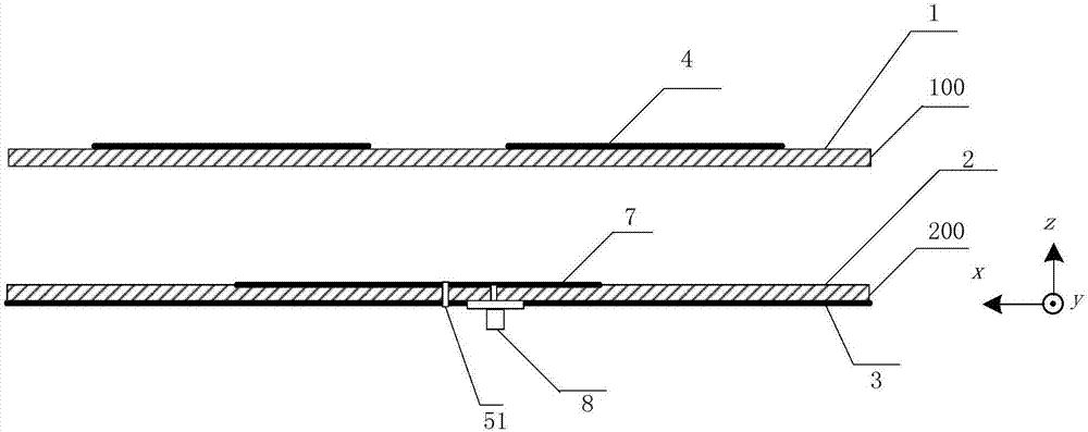
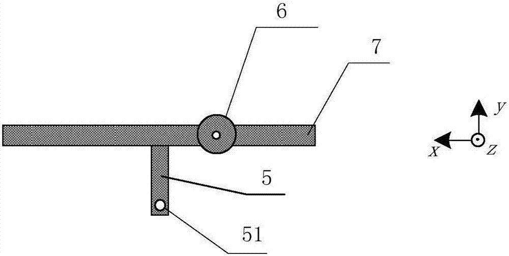
The invention discloses a low profile dipole antenna comprising an upper layer structure having a dipole, a middle layer structure, and a lower layer structure having a metal ground; the middle layer structure is provided with a semi-wavelength open circuit resonator connected with a feed structure, so the microwave signal can be coupled to the dipole, thus realizing the antenna low profile structure, developing the bandwidth, and improving the high end out of band rejection level; furthermore, the middle layer structure is provided with a short circuit branch so as to form a frequency low end radiation zero point, thus improving the antenna low end out of band rejection level, and realizing the antenna filtering function; compared with the conventional dipole antenna low profile technology, the low profile dipole antenna can realize antenna low profile design without increasing antenna sizes, and a filter function can be obtained; the bandwidth can be also improved when compared with a conventional dipole antenna of the same thickness.

Description

technical field [0001] The invention relates to the field of microwave communication, in particular to a low profile dipole antenna. Background technique [0002] Generally speaking, the impedance matching bandwidth of a dipole antenna is narrow, and the distance between the antenna and the ground needs to satisfy λ 0 / 4, when the height is reduced, it will seriously affect the radiation impedance, gain and impedance matching performance of the antenna, which is not conducive to the practical application of dipole antennas. The technologies usually used to reduce the height of the antenna section are mainly artificial magnetic conductor technology, electromagnetic bandgap technology and high-resistance surface technology, but its periodic structure makes its processing complex and the antenna area is large. Therefore, the small size and low profile dipole antenna is very important. [0003] In addition, with the rapid development of communication technology, the requiremen...

Claims


Application Information

Patent Timeline
Patent Type & Authority Applications(China)
IPC IPC(8): H01Q1/38H01Q1/50H01Q9/20
CPCH01Q1/38H01Q1/50H01Q9/20
Inventor 施金张诚曹青华张威陈建新秦伟包志华
Owner NANTONG RES INST FOR ADVANCED COMM TECH CO LTD
Learn More