Novel auxiliary reflecting face supporting satellite borne ring focus antenna
A space-borne ring focus and antenna technology, which is applied in the directions of antenna, antenna support/installation device, radiation unit cover, etc., can solve the problems of large loss, complicated preparation method of dielectric cover material, and influence on antenna radiation efficiency, etc., and achieve low loss , increase the difficulty of installation, the effect of strong space adaptability
- Summary
- Abstract
- Description
- Claims
- Application Information
AI Technical Summary
Problems solved by technology
Method used
Image
Examples
Embodiment 1
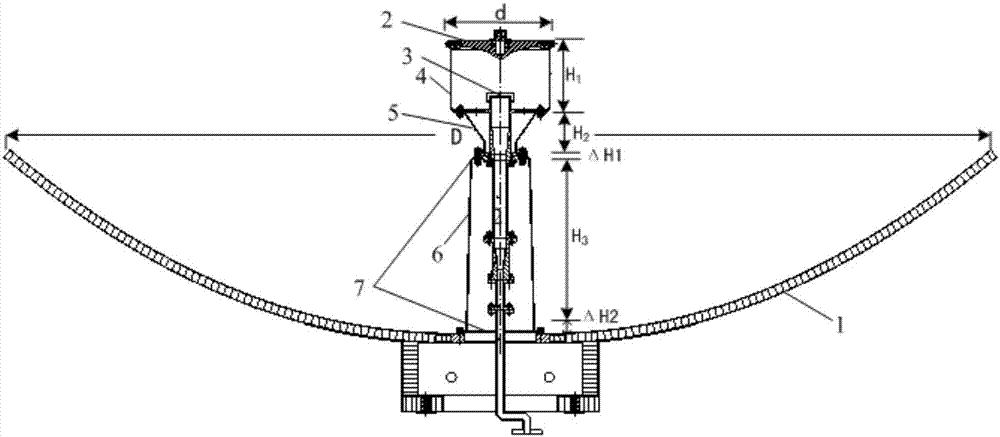
[0028] see figure 1 , the space-borne ring-focus antenna based on the new type of supporting sub-reflector described in the present invention includes a main reflector 1, a sub-reflector 2, a feed source assembly 3, a cylindrical dielectric cover 4, a circular frustum dielectric cover 5, an adjusting gasket 7 and a center The support cover, the feed source assembly 3 is installed on the central support barrel 6, the cylindrical dielectric cover 4 is tightly connected with the secondary reflector 2 and then fixed with the round table dielectric cover 5 by screws and then installed on the central support barrel 6, the central support barrel 6 Adjusting gaskets 7 are added between the round frustum dielectric cover 5, and finally it is connected and fixed with the main reflective surface 1.
Embodiment 2
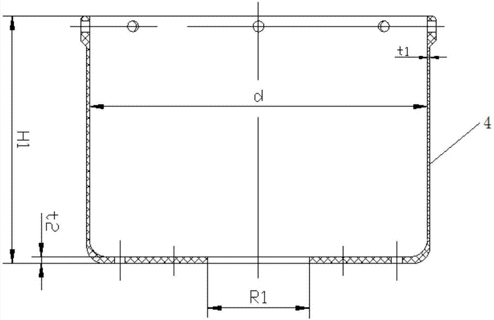
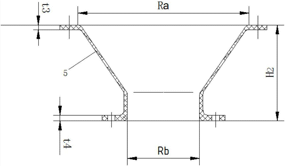
[0030] see Figure 1 to Figure 5 , this embodiment is an improvement made on the basis of Embodiment 1, in particular, the sub-reflector 2 is an elliptical surface of revolution made of metal, and its diameter is d=6.75λ 0 ,λ 0 is the wavelength of the center frequency electromagnetic wave, and the elliptic generatrix equation is -3.10λ 0 ≤X≤3.10λ 0 , -2.37λ 0 ≤Y≤2.37λ 0 ; The main reflector 1 is an aluminum honeycomb rotating paraboloid made of carbon fiber, and its diameter is D=67.5λ 0 , the focal length is F=18.23λ 0 , the parabolic generatrix equation is (X-d / 2) 2 =4×F×Z, Z≥0, X∈R (that is, X is a real number); the feed source component 3 is an axial groove corrugated horn, and the radius of the horn mouth surface r=1.92λ 0 , using BJ180 waveguide for circular polarization feeding; the cylindrical dielectric cover 4 is made of polyimide material, and its aperture size is about 6.75λ 0 , which is the same as the diameter d of the sub-reflector 2, and the height i...
Embodiment 3
[0032] see Figure 1 to Figure 5 , the present embodiment is an improvement made on the basis of the embodiment, wherein the sub-reflector 2 is an elliptical surface of revolution made of metal, its diameter is d=100mm, and the ellipse generatrix equation is -3.10λ 0 ≤X≤3.10λ 0 , -2.37λ 0 ≤Y≤2.37λ 0 ; The main reflector 1 is an aluminum honeycomb rotating paraboloid of carbon fiber material, its diameter is D=1000mm, the focal length is F=270mm, and the parabola generatrix equation is (X-d / 2) 2 =4×F×Z, Z≥0, X∈R (that is, X is a real number); the feed component 3 is an axial groove corrugated horn, the radius of the horn mouth is r=28.5mm, and the BJ180 waveguide is used for circularly polarized feed Electricity: Cylindrical dielectric cover 4 is made of polyimide material, its aperture size is the same as the diameter d of the secondary reflector 2, the height is H1=73mm, the side wall thickness t1=0.8mm, the bottom surface thickness t2=2mm, and the diameter R1=30mm roun...
PUM
 Abstract
Description
Claims
Application Information
 - Generate Ideas
- Intellectual Property
- Life Sciences
- Materials
- Tech Scout
- Unparalleled Data Quality
- Higher Quality Content
- 60% Fewer Hallucinations
Browse by: Latest US Patents, China's latest patents, Technical Efficacy Thesaurus, Application Domain, Technology Topic, Popular Technical Reports.
© 2025 PatSnap. All rights reserved.Legal|Privacy policy|Modern Slavery Act Transparency Statement|Sitemap|About US| Contact US: help@patsnap.com


