
Rotary type hydraulic valve

A hydraulic valve, rotary technology, applied in the field of rotary hydraulic valves, can solve the problems of large volume, uneconomical, enlarged diameter, etc.

Inactive Publication Date: 2017-07-18
郑瑞源
View PDF5 Cites 3 Cited by
  • Summary
  • Abstract
  • Description
  • Claims
  • Application Information

AI Technical Summary

Problems solved by technology

[0002] The existing hydraulic system (Hydraulic System) adopts "Pascal's Law (also known as Pascal's Principle)" to amplify the force. According to Pascal's Principle: "For fluids in closed containers that do not undergo volume changes due to pressure When pressure is applied, this pressure can be transmitted to other parts of the fluid, and its pressure intensity remains unchanged", and the directional control valve of the hydraulic system is the control mechanism of the hydraulic system, which is responsible for controlling and regulating the oil pressure and flow in the oil circuit. and guiding, which can transmit energy, and then make the actuator achieve a predetermined action, such as: jack lifting, actuators that can convert energy into mechanical motion (such as: linear motion hydraulic cylinders and rotary motion hydraulic motors), The realization of various actions of cranes or excavators; however, if the directional control valve of the traditional hydraulic system is a plate valve, because the valve core controls the flow direction of the hydraulic oil in a linear sliding manner, not only the internal leakage of the hydraulic oil And the pressure loss is relatively high, and it is necessary to add a valve block as a transfer connection of the oil pipe, so that the volume is too large, heavy, and the cost is high; if the traditional electromagnetic reversing valve is not suitable for large flow Hydraulic machinery, because if you want to overcome the stability of large flow fluid force, hydraulic clamping force, motion friction resistance, and the reaction force of the return spring, you must increase the thrust of the electromagnet, which will cause the electromagnet to be too large , and to reduce the loss of pressure, it is necessary to increase the diameter of the spool, which is not in line with economic benefits; from the above, these shortcomings bring great inconvenience and trouble to the users of the hydraulic system

Method used


Image

  • Rotary type hydraulic valve
  • Rotary type hydraulic valve
  • Rotary type hydraulic valve

Examples


Embodiment Construction

[0055] In order to further understand the structure, features and functions of the present invention, preferred embodiments are attached herewith and detailed descriptions are as follows in conjunction with the accompanying drawings.

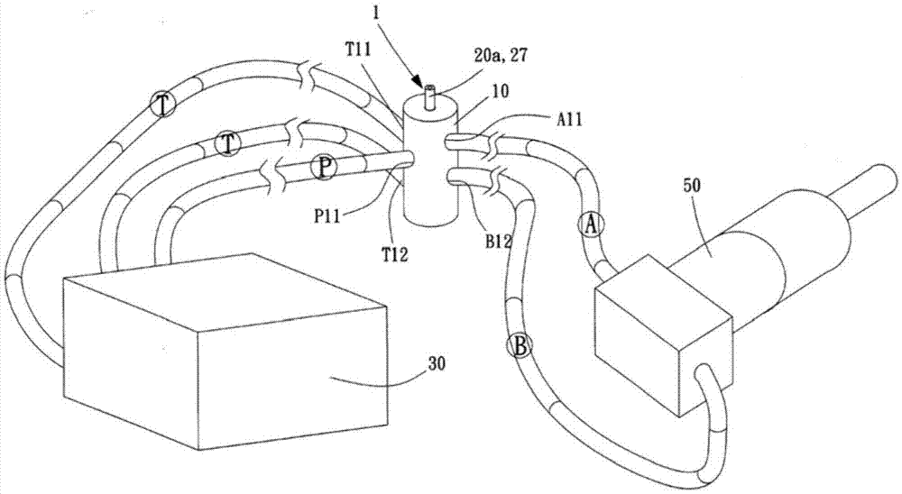
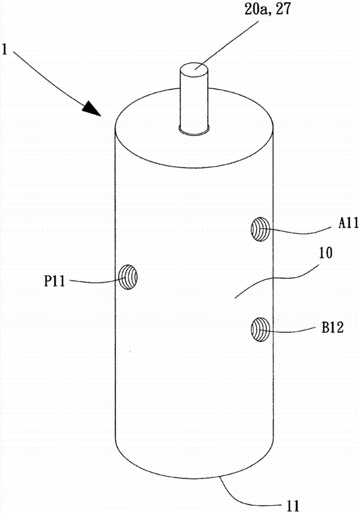
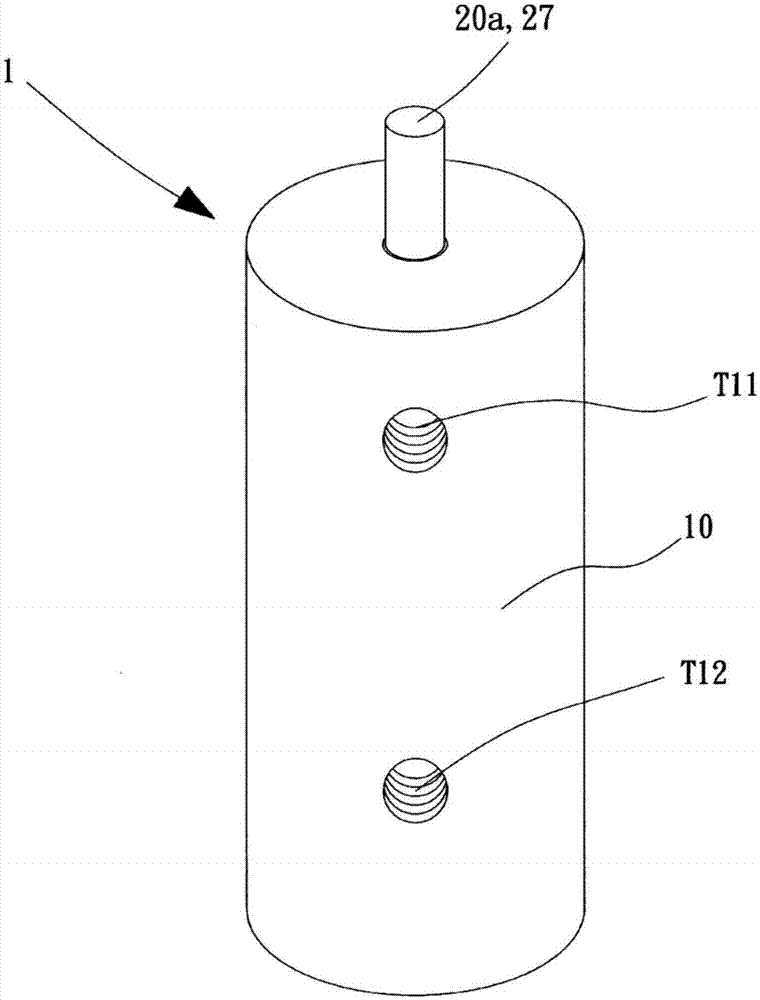
[0056] see figure 1 , figure 2 , image 3 , Figure 4 , Figure 5 , Figure 6 as well as Figure 7 As shown, the rotary hydraulic valve 1 of the present invention mainly includes a valve body 10 with a rotating space 100 inside and a sealed upper part and a valve core 20a with a shaft 20; The oil inlet outer hole P11, the first working outer hole A11, the second working outer hole B12, the first oil return outer hole T11, and the second oil return outer hole T12 of the rotating space 100; wherein, the oil inlet outer hole P11, the second oil return outer hole The first oil return outer hole T11 and the second oil return outer hole T12 are connected to the oil pressure source 30, the first working outer hole A11 and the second working oute...


PUM


Abstract

The invention relates to a rotary type hydraulic valve. The rotary type hydraulic valve comprises a valve body and a valve core rotationally and axially arranged in a rotating space of the valve body. When flowing into an oil inlet pressure balancing hole of the valve core from an oil inlet outer hole, hydraulic oil of an oil pressure source fills an annular groove of the oil inlet pressure balancing hole at any time and then flows into open inverted U-shaped grooves and open U-shaped grooves of a first working part and open inverted U-shaped grooves and open U-shaped grooves of a second working part, so that the upper force potential difference and the lower force potential difference of the valve core are symmetrically balanced; when all outer holes of the valve body communicate with all inner holes of the valve core, the hydraulic oil flows into a first oil return annular groove, a second oil return annular groove as well as the open U-shaped grooves and the open inverted U-shaped grooves of the first and second working parts; the pressure of the hydraulic oil acts on the inner wall of the valve body at any time; the compactness between the valve core and the valve body can be more precise; the inner leakage quantity of the hydraulic oil reaches the minimum; and in addition, the valve core can be suspended and kept balanced at any time and can be easily rotated with very small acting force so that the direction of a shaft part can be changed, the flow rate of the hydraulic oil is controlled, the hydraulic oil smoothly flows in the predetermined direction, and the predetermined action of an actuator is controlled.

Description

technical field [0001] The invention relates to a rotary hydraulic valve, specifically referring to a control valve of a hydraulic system, especially a rotary hydraulic valve whose spool can keep balance at any time, and can easily change the fluid direction and effectively control the flow rate by rotating . Background technique [0002] The existing hydraulic system (Hydraulic System) adopts "Pascal's Law (also known as Pascal's Principle)" to amplify the force. According to Pascal's Principle: "For fluids in closed containers that do not undergo volume changes due to pressure When pressure is applied, this pressure can be transmitted to other parts of the fluid, and its pressure intensity remains unchanged", and the directional control valve of the hydraulic system is the control mechanism of the hydraulic system, which is responsible for controlling and regulating the oil pressure and flow in the oil circuit. and guiding, which can transmit energy, and then make the act...

Claims


Application Information

Patent Timeline
IPC IPC(8): F15B13/02F16K11/085
CPCF15B13/02F16K11/0856
Inventor 郑瑞源
Owner 郑瑞源
Learn More