
Double-oil-way jet integrated afterburner

A technology of afterburner and double oil circuit, which is applied in the direction of combustion chamber, continuous combustion chamber, combustion method, etc. It can solve the problems of affecting the normal operation of the combustion chamber and the system, poor atomization effect, and affecting the effect of atomization and evaporation. Achieve the effects of improving combustion efficiency and combustion stability, enhancing fuel atomization effect, and improving infrared stealth performance

Inactive Publication Date: 2017-07-14
NORTHWESTERN POLYTECHNICAL UNIV
View PDF2 Cites 5 Cited by
  • Summary
  • Abstract
  • Description
  • Claims
  • Application Information

AI Technical Summary

Problems solved by technology

This phenomenon will cause the combustion device and even the whole system to vibrate violently, emit huge noise, increase the heat load, aggravate the generation of pollutants, affect the normal operation of the combustion chamber and the system, and even cause damage and destruction of system components in severe cases
[0005] For the afterburner, the improvement of fuel combustion efficiency and combustion stability is very important. The fuel oil circuit design and injection method are different, which can greatly affect the atomization and evaporation effect of the fuel in the afterburner, thereby further affecting the combustion. Indoor combustion efficiency and combustion stability
At present, most of the integrated afterburner fuel injection methods are simple, and the atomization effect is poor. To improve the afterburner performance, further in-depth research on fuel injection methods is needed.

Method used


Image

  • Double-oil-way jet integrated afterburner
  • Double-oil-way jet integrated afterburner
  • Double-oil-way jet integrated afterburner

Examples


Embodiment Construction

[0025] The present invention will be further described now in conjunction with accompanying drawing:

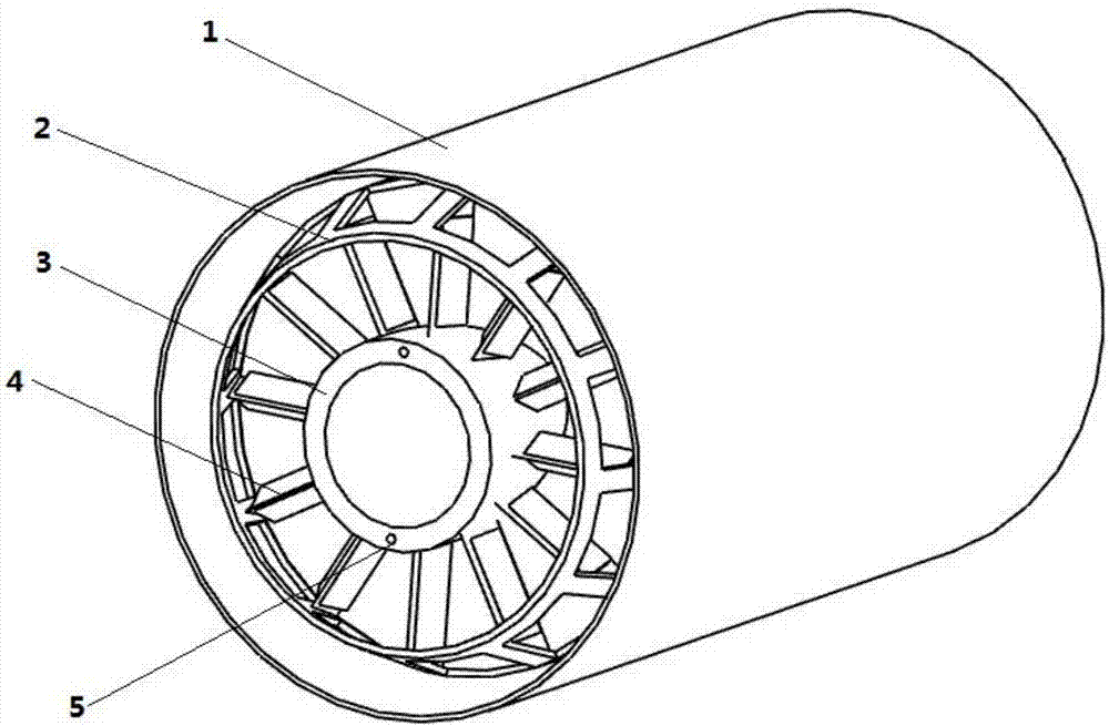
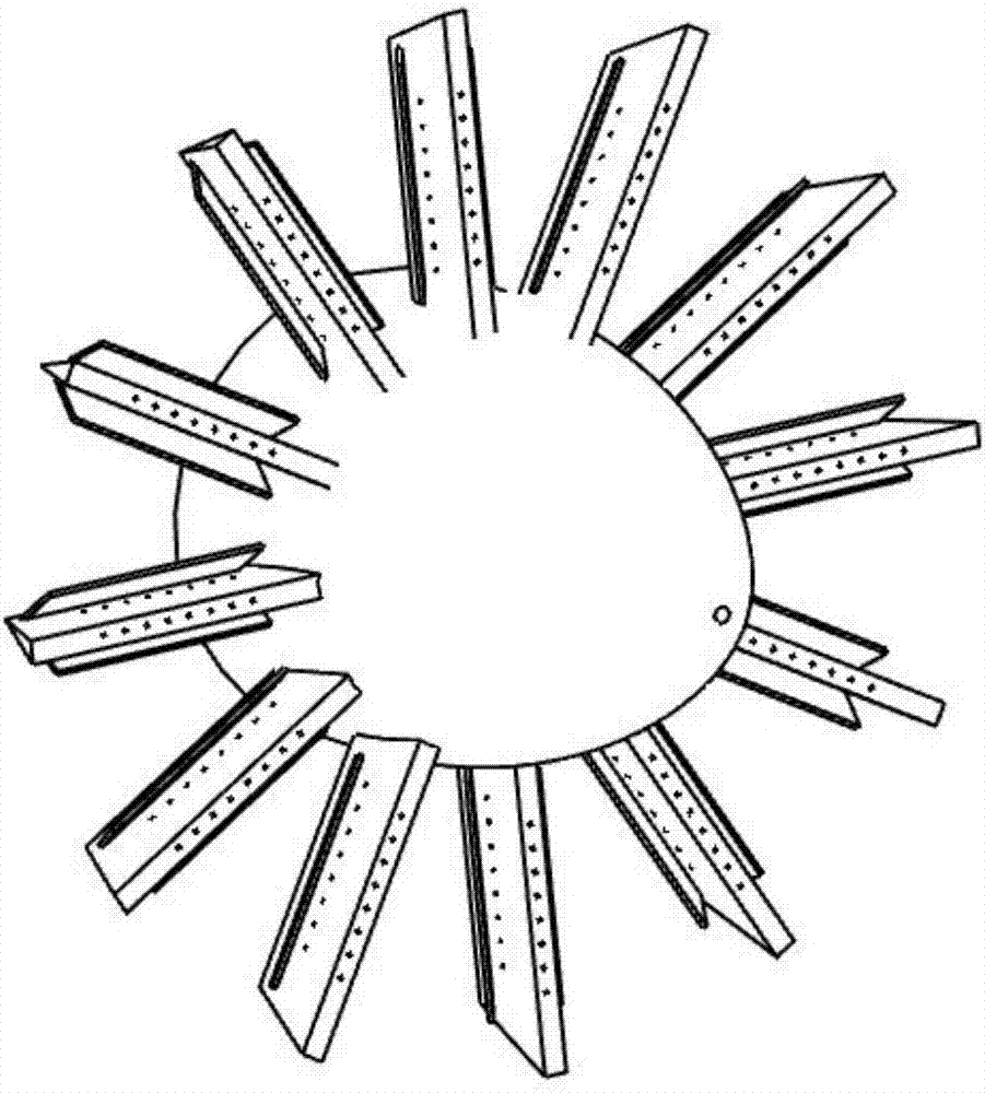
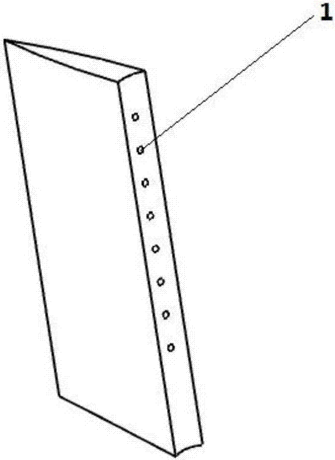
[0026] combine figure 1 , figure 2 , image 3 , Figure 4 , The present invention provides an integrated afterburner with a new type of fuel injection. The injection mode is a dual oil circuit injection mode, and the fuel is injected at the center of the tail of the flame stabilizer of the rectifying support plate and the center of the afterburner inner cone. figure 1 It is a three-dimensional schematic diagram of the afterburner integrated with dual oil circuit injection, figure 2 It is a three-dimensional schematic diagram of the rectifying strut flame stabilizer and the afterburner inner cone, image 3 A schematic diagram of a flame holder with a single rectifying strut, Figure 4 It is a schematic cross-sectional view of a single rectifying strut flame stabilizer and afterburner inner cone.

[0027] fuel from figure 1 The oil inlet hole shown in (5) enters figur...


PUM


Abstract

The invention provides a double-oil-way jet integrated afterburner. A double-oil-way jet mode is adopted in the integrated afterburner. Jet positions for fuel oil jetting are the central position of the tail of a fairing spoke flameholder and the central position of a thrust augmentation inner cone. Compared with the prior art, the fuel oil jetting mode is changed, and as for an outer oil way, the jetted fuel oil is mixed with high-temperature mixed gas, and the atomizing effect is improved under the effect of the shear force of the high-temperature mixed gas; and as for a central oil way, since the thrust augmentation inner cone enables a wide low-speed backflow area to be formed behind the afterburner, the jetted fuel oil of the part is fully mixed with high-temperature mixed gas in the low-speed area, and the premixing effect is enhanced. Combustion is jointly conducted through the two oil ways in the afterburner, so that the combustion efficiency of the afterburner is improved, and the combustion stability is good. Meanwhile, the fuel oil can effectively decrease the temperature of the thrust augmentation inner cone to improve the infrared stealth performance of an engine.

Description

technical field [0001] The invention belongs to the field of gas turbine engines, and in particular relates to an integrated afterburner in a novel fuel injection mode. Background technique [0002] The power plant of military fighter jets often increases thrust through the afterburner. At present, the power units of the main fighters in active service of the air forces of various countries in the world all use afterburning turbofan engines. The afterburner is located between the gas turbine and the nozzle, and is an important part of the aero engine. By injecting additional fuel into the high-temperature and high-speed gas flowing out of the turbine, it can greatly increase the temperature of the gas and increase the thrust of the engine in a short time. Generally, the airflow entering the afterburner first passes through a diffuser to reduce the velocity of the flow. But even after diffusion, the gas flow rate is still too high for combustion. In order to solve the probl...

Claims


Application Information

Patent Timeline
Patent Type & Authority Applications(China)
IPC IPC(8): F23R3/28
CPCF23R3/28
Inventor 张群黎超超寇睿宋亚恒李承钰李逸飞
Owner NORTHWESTERN POLYTECHNICAL UNIV
Learn More