Control device of a powertrain with a centrifugal pendulum damper

A technology of power transmission system and control device, applied in vibration suppression adjustment, rotational vibration suppression, clutch, etc., can solve the problems of reducing the reliability of centrifugal vibrator shock absorbers, and achieve the effect of improving fuel consumption performance and avoiding reliability reduction.

Inactive Publication Date: 2017-07-14
MAZDA MOTOR CORP
View PDF6 Cites 0 Cited by
  • Summary
  • Abstract
  • Description
  • Claims
  • Application Information

AI Technical Summary

Problems solved by technology

[0009] The present invention is formed in view of the above-mentioned actual situation about the control device of the power transmission system with the ce...

Method used


Image

  • Control device of a powertrain with a centrifugal pendulum damper
  • Control device of a powertrain with a centrifugal pendulum damper
  • Control device of a powertrain with a centrifugal pendulum damper

Examples


Embodiment Construction

[0055] Embodiments of the present invention will be described below.

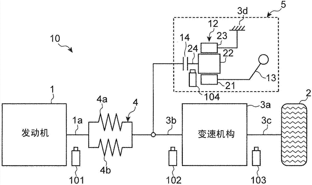
[0056] figure 1 It is a schematic diagram showing the configuration of a powertrain 10 with a centrifugal vibrator damper (hereinafter, simply referred to as “powertrain 10 ”) according to an embodiment of the present invention. Such as figure 1 As shown, the power transmission system 10 includes: an engine 1, a transmission mechanism 3a of an automatic transmission 3 that transmits the driving force of the engine 1 to the drive wheels 2, and an output shaft 1a of the engine 1 and an input shaft 3b of the transmission mechanism 3a. The torsional damper mechanism 4 connected therebetween, and the centrifugal vibrator damper mechanism 5 connected to the input shaft 3b of the transmission mechanism 3a.

[0057] The automatic transmission 3 is a stepped transmission including a transmission mechanism 3 a that selectively tightens a plurality of friction fastening elements to switch gear ratios in steps. In a...


PUM


Abstract

The invention relates to a control device of a powertrain with a centrifugal pendulum damper, and the control device can avoid reliability reduction caused by high-speed revolution of the centrifugal pendulum damper. The control device (100) of the powertrain (10) with a centrifugal pendulum damper is provided in which the centrifugal pendulum damper (13) and a power transmission shaft (3b) are operatively coupled via a clutch mechanism (14), and the control device of the powertrain with the centrifugal pendulum damper includes a connection/disconnection control portion (130) for controlling an engagement degree of the clutch mechanism (14) by controlling the engagement degree of the clutch mechanism (14) such that the centrifugal pendulum damper (13) rotates at or below an predetermined upper rotational speed limit.

Description

technical field [0001] The present invention relates to a control device for a power transmission system of a vehicle, and more particularly, to a control device for a power transmission system having a centrifugal vibrator damper. Background technique [0002] Conventionally, in a vehicle equipped with a power transmission system constituting a power transmission path from the engine through an automatic transmission to the drive wheels, in order to improve the fuel consumption performance of the engine, it is known to use reduced-cylinder operation of the engine, HCCI combustion, and abolished torque conversion. Torque converter-free automatic transmission and other technologies. [0003] However, there is a problem that the fluctuation of the output torque becomes large in the engine that adopts reduced-cylinder operation and HCCI combustion. In addition, when the automatic transmission is used without a torque converter, the torque fluctuation of the engine is output fro...

Claims


Application Information

Patent Timeline
IPC IPC(8): F16F15/14F16F15/134
CPCF16F15/134F16F15/1478F16D2500/1066F16D2500/30415F16D2500/30426F16D2500/3067F16D2500/50293F16D2500/7041F16D2500/70426F16D48/06F16F15/002F16F15/145F16D2300/22F16D2500/10412F16D2500/1045F16D2500/30401F16D2500/306F16D2500/316
Inventor 中岛亨成中山康成齐藤忠志仲岸优堂面成史本瓦成人
Owner MAZDA MOTOR CORP
Why Eureka
Try Eureka