Rotary vane type viscous damper

A viscous damper and rotary vane technology, which is applied in the direction of protective buildings/shelters, building components, building types, etc., can solve problems such as insufficient spring stiffness, failure to reach, and vacuum generated by the oil cylinder, etc., to improve vibration The effect of controlling efficiency, improving anti-seismic effect, and flexible layout position

Inactive Publication Date: 2017-07-14
TONGJI UNIV
View PDF4 Cites 14 Cited by
  • Summary
  • Abstract
  • Description
  • Claims
  • Application Information

AI Technical Summary

Problems solved by technology

[0004] However, the current viscous dampers still have certain deficiencies: (1) The early viscous dampers are usually in the form of a single rod. When the piston moves, the viscous fluid in the cylinder is actually a compressible material, so that When the piston rod is pulled out, the volume occupied by the extracted part of the piston rod in the cylinder cannot be compensated immediately, and a vacuum phenomenon will be generated in the cylinder, so that the piston rod cannot continue to move; The viscous fluid part of one side of the oil cylinder enters the oil cylinder, but the volume of the oil cylinder does not increase, which leads to the top dead phenomenon; (2) It is known from the test that the damping force of the damper under the small stroke condition cannot reach the level determined by the The performance given by the theoretical formula of the damper cannot achieve the very high damping ratio calculated by the theoretical formula when the displacement is small under the action of an earthquake. viscous mechanical behavior

Method used


Image

  • Rotary vane type viscous damper
  • Rotary vane type viscous damper
  • Rotary vane type viscous damper

Examples


Embodiment 1

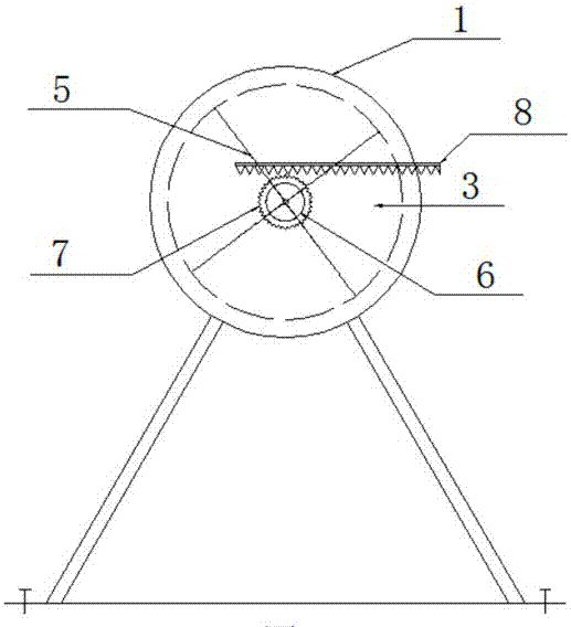
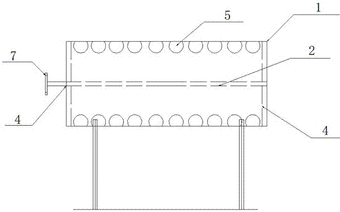
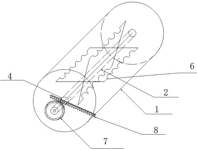
[0022] Embodiment 1: as figure 1 Shown is an embodiment of a rotary vane viscous damper of the present invention, which mainly includes a gear transmission amplifier and a rotary vane damper. The gear transmission amplification device consists of a rotating shaft 2, a damper connector 4, a transmission gear 7 and an input rod 8, and the rotary vane viscous damper is composed of a cylindrical box 1, a viscous liquid 3, a rotating blade 5, and a flow hole 6 .

[0023] Cylindrical box 1 has a radius of 200mm and a length of 800mm, and contains a viscous liquid 3 inside; the rotating shaft 2 has a radius of 25mm and a length of 900mm, and is installed on the box 1 through a leading port; the rotating shaft 2 is located in the box The part inside the body 1 can be installed with one or more rotating blades 5, the length of the rotating blade 5 is 800mm, the width is 200mm, and a circle of circular flow holes 6 is opened on the edge; Connect transmission gear 7, its radius is 500m...


PUM


Abstract

The invention relates to a rotary vane type viscous damper which comprises a gear transmission amplification device and a rotary vane type viscous damper body. The gear transmission amplification device is composed of a closed protective shell, damper connecting pieces, an acceleration transmission system and an input rod. Leading connectors and rotating shafts are arranged on the damper connecting pieces; a row of tooth structures with large curvature are arranged on the upper portion of the input rod; and the acceleration transmission system is composed of an input rod tooth structure, a transmission gear and rotary vanes, the input rod tooth structure is engaged with the transmission gear, and the transmission gear and the rotary vanes rotate coaxially. The rotary vane type viscous damper body is composed of a cylindrical closed box body, viscous liquid inside the box body and the rotary vanes provided with circulation holes in the outer side. Under the action of wind or / and an earthquake and the like, by means of the relative displacement of gear transmission base / floors, the radius ratios of the transmission gear and the rotary vanes are arranged to amplify linear displacement of the outer sides of the vanes, and the viscous liquid inside the box body is forced to generate a certain flow rate through the circulation holes in a short time to dissipate energy. The rotary vane type viscous damper can effectively improve the vibration control efficiency of the building structure when deformation of the building structure is less or slow.

Description

technical field [0001] The invention relates to a rotary vane viscous damper, in particular to a rotary vane viscous damper equipped with an amplifying device, which combines the advantages of a viscous damper and a gear transmission displacement / velocity amplifying device, effectively improving the Damper shock absorption effect. It belongs to the field of vibration control of civil structures (including high-rise buildings, towering structures, etc.). Background technique [0002] In recent years, passive control technologies such as base isolation, energy dissipation, and tuned vibration control have been widely used in civil engineering at home and abroad because of their simple concept, clear mechanism, low cost, and remarkable shock absorption effect. Among them, the viscous damper has attracted the attention of civil engineering researchers because of its good economy, good applicability and low maintenance cost. [0003] The common viscous damper is hydraulic cylin...

Claims


Application Information

Patent Timeline
Patent Type & Authority Applications(China)
IPC IPC(8): E04H9/02E04B1/98
CPCE04H9/021E04H9/0235
Inventor 鲁正李依文王梓芃周中通
Owner TONGJI UNIV
Why Eureka
Try Eureka