Extrusion type bi-trunking milling tool absorber

A technology for milling tools and double-line grooves, which is applied to milling machine equipment, manufacturing tools, milling machine equipment details, etc., can solve problems such as practical difficulties, difficult realization, and fragility

Inactive Publication Date: 2017-07-14
HARBIN UNIV OF SCI & TECH
View PDF0 Cites 1 Cited by
  • Summary
  • Abstract
  • Description
  • Claims
  • Application Information

AI Technical Summary

Problems solved by technology

One is that piezoelectric ceramics need a higher control voltage as an actuator, and there are certain difficulties in practical use; the other is that piezoelectric ceramics are poorly flexible and fragile, and are not suitable for occasions that are subject to large impacts.
[5] In the

Method used


Image

  • Extrusion type bi-trunking milling tool absorber
  • Extrusion type bi-trunking milling tool absorber
  • Extrusion type bi-trunking milling tool absorber

Examples


Embodiment Construction

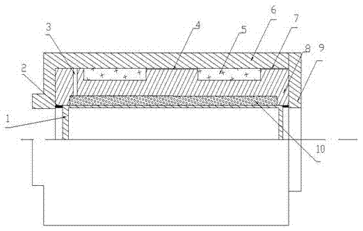
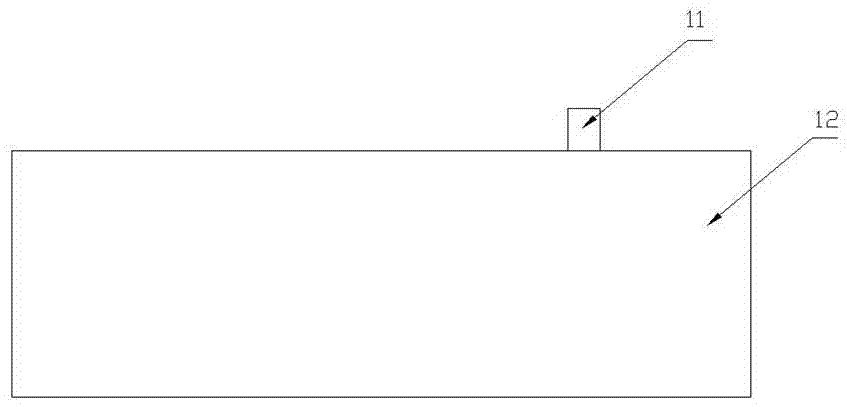
[0013] Such as figure 1 , figure 2 , image 3 As shown, the patent of the present invention includes 1 inner shaft sleeve, 2 mechanical seals, 3 liquid injection holes, 4, (7) wiring slots, 5 double coil slots, 6 clamping shaft sleeves, 8 core bodies, 9 end caps, 10 magnetorheological fluid, 11 displacement sensor, 12 milling tool, 13 signal conditioner, 14 analog-to-digital converter A / D, 15 control chip, 16 digital-to-analog converter D / A, 17 power amplifier.

[0014] Such as figure 1 As shown, the inner shaft sleeve 1 is installed into the core body 8 by a cold fitting method to form a through annular cavity. The magnetorheological fluid 10 is injected into the annular cavity through the injection hole 3 . In the two coil slots 5, 60 turns of enameled wire with a nominal diameter of 0.8 mm and a DC resistance of 34.8 ohms per kilometer are respectively wound to form an excitation coil. The lead-out wires of the excitation coil lead out of the shock absorber through th...


PUM


Abstract

The invention discloses an extrusion type bi-trunking milling tool absorber. According to the absorber, the principle that under the action of an electromagnetic field, magnetorheological fluid can produce extrusion acting force within several milliseconds is applied, the inherent frequency of a milling tool is improved, and acute vibration of the milling tool is avoided. The absorber is provided with an inner shaft sleeve, mechanical seals, an injection hole, wireways, a double-coil groove, a clamping shaft sleeve, a core body, a magnet exciting coil, an end cover and the magnetorheological fluid. The injection hole is machined in the tail end of the core body of the absorber, convenient injection and replacing of the magnetorheological fluid are achieved, and the machining process and the using efficiency of the absorber are improved. By means of the wireways in the outer side face of the core body of the absorber, reasonable layout of a lead of the magnet exciting coil is achieved, and the intervene problem between the lead and the clamping shaft sleeve and the end cover is avoided. By means of the inner shaft sleeve, the magnetorheological fluid and the milling tool are separated, the situation that impurities in the working environment pollutes the magnetorheological fluid is avoided, and rapid dismounting and mounting of the milling tool is achieved.

Description

technical field [0001] The patent of the present invention relates to a technology for reducing the vibration of a milling tool in the field of mechanical processing during processing a workpiece. Background technique [0002] In the machining process, due to the insufficient structural rigidity of the milling system and the interaction of internal excitation and feedback, strong vibrations often occur between the workpiece and the tool, especially when the length-to-diameter ratio of the tool is greater than 5, the cutting force is small In the case of , you will still encounter problems with flutter. These vibrations not only adversely affect the roughness of the machined surface and machining accuracy, but also generate environmental noise and damage tools and machine tools. In order to solve the problem of milling vibration, many scholars at home and abroad have done a lot of research: [1] American scholar Taylor believes that cutting vibration is due to the fact that t...

Claims


Application Information

Patent Timeline
IPC IPC(8): B23Q11/00B23C9/00
CPCB23Q11/0039B23C9/00
Inventor 隋秀凛陈彬葛江华王亚萍陈晓奇陈云壮廉冲
Owner HARBIN UNIV OF SCI & TECH
Why Eureka
Try Eureka