Tubular workpiece quality testing device
A workpiece and tubular technology, applied in the field of tubular workpiece quality inspection devices, can solve the problems of unsaleable pipe fittings and high testing costs, and achieve the effects of reducing re-cleaning, improving production efficiency, and improving quality inspection accuracy
- Summary
- Abstract
- Description
- Claims
- Application Information
AI Technical Summary
Problems solved by technology
Method used
Image
Examples
Embodiment 1
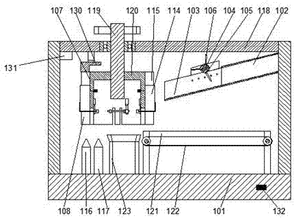
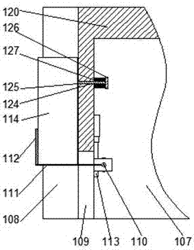
[0033] In this embodiment, in order to facilitate the rotation of the disk, a preferred structure for starting the rotation of the disk is disclosed. Preferably, an upper top cover 118 is arranged above the support frame 101, so that the upper top cover is suspended relative to the support frame. A space for processing the pipe body is formed between the upper top cover and the support frame. A main shaft 119 is arranged on the upper top cover 118 so that the main shaft is rotatably connected to the upper top cover through a bearing. A platform 120 is provided on the inner side of the upper end of the disk 107, and the lower end of the main shaft 119 is sleeved on the inner side of the platform 120, so that the platform and the main shaft are fixed to each other. When the motor rotates, the main shaft is started to rotate synchronously, and at this time, the main shaft starts the disc to rotate.
Embodiment 2
[0035] Due to the light weight of the workpiece, it may fall off from the retaining part during cleaning or drying. This embodiment is based on Embodiment 1, in order to prevent the workpiece from above the retaining part under the action of water or wind. Move out, preferably, a press-fit cover 130 is provided above the disc 107. When the disc rotates, the lower end surface of the press-fit cover is suspended relative to the disc, and an air pressure is provided on the lower end face of the upper top cover 118. Cylinder, the pneumatic rod of the pneumatic cylinder is fixedly connected to the upper end surface of the press-fit cover 130, so that the press-fit cover 130 is located between the water outlet nozzle 116 and the air outlet. Above the nozzle 117, when spraying water to the inside of the pipe body, use the press-fit cover to fix the bottom of the pipe body to keep it stable and prevent it from moving out from above the retaining part. When drying, use the press-fit co...
Embodiment 3
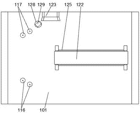
[0037] In this embodiment, in order to facilitate the collection of unqualified pipes, preferably, two fences 121 are arranged on the support frame 101 on one side of the passage trough 103, so that the two fences are parallel to each other , A conveyor belt 122 is set between the two fences 121, the pipe body falling from the discharge chute enters the inner side of the fence, and is transported out through the conveyor belt inside the fence for centralized processing.
[0038] In this embodiment, in order to facilitate the collection of the cleaned tubes, preferably, an outlet 123 is provided on one side of the support frame 101, and the delivery point of the outlet 123 is located below the disc 107, After the tube body is moved out of the retaining part, it falls into the outlet to facilitate directional output.
PUM
 Abstract
Description
Claims
Application Information
 - R&D Engineer
- R&D Manager
- IP Professional
- Industry Leading Data Capabilities
- Powerful AI technology
- Patent DNA Extraction
Browse by: Latest US Patents, China's latest patents, Technical Efficacy Thesaurus, Application Domain, Technology Topic, Popular Technical Reports.
© 2024 PatSnap. All rights reserved.Legal|Privacy policy|Modern Slavery Act Transparency Statement|Sitemap|About US| Contact US: help@patsnap.com


