Wide-body steel main girder erecting machine and erecting method thereof

A wide-body steel and main girder frame technology, which is applied to bridges, bridge construction, erection/assembly of bridges, etc., can solve problems such as broken and dropped concrete blocks, large blocks, limited support space, and foundation bearing capacity, achieving The effect of reducing the weight of the whole machine, improving the overall stability and improving efficiency

Inactive Publication Date: 2017-07-11
WUHAN BRIDGE SPECIAL TECH CO LTD CHINA RAILWAY MAJOR BRIDGE ENG BUREAU +1
View PDF5 Cites 6 Cited by
  • Summary
  • Abstract
  • Description
  • Claims
  • Application Information

AI Technical Summary

Problems solved by technology

The bridge decks of existing bridges and highways are generally concrete structures. Long-term use will cause local concrete blocks to be damaged and fall off, causing serious safety hazards to the operation of railway business lines. The replacement of bridge decks has become one of the important contents of this type of bridge maintenance.
[0003] New bridge decks usually use long-lived orthotropic steel girder decks (hereinafter referred to as steel girders). Due to the limitations of existing bridge structures and the requirements for installation efficiency, the new steel girders are often divided into larger pieces, and in Affected by various aspects such as railway business lines, road traffic, and waterway transportation during erection, there are problems such as limited support space, foundation bearing capacity, and unusable large-scale equipment, which makes the traditional steel main girder erection method unable to meet the process requirements

Method used


Image

  • Wide-body steel main girder erecting machine and erecting method thereof
  • Wide-body steel main girder erecting machine and erecting method thereof
  • Wide-body steel main girder erecting machine and erecting method thereof

Examples


Embodiment Construction

[0046] The present invention will be described in further detail below in conjunction with the accompanying drawings.

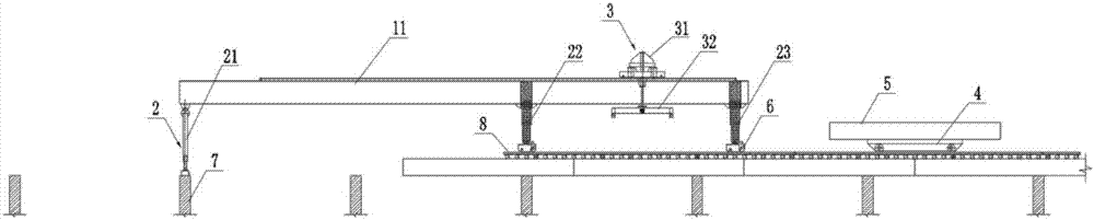
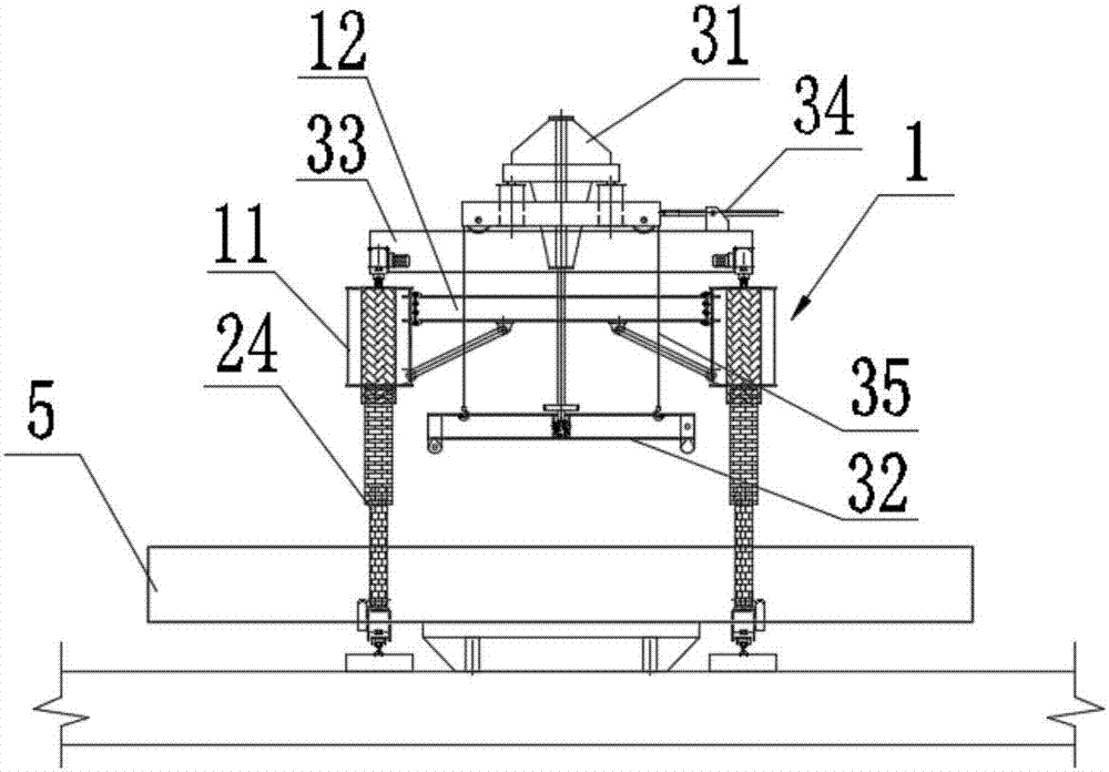
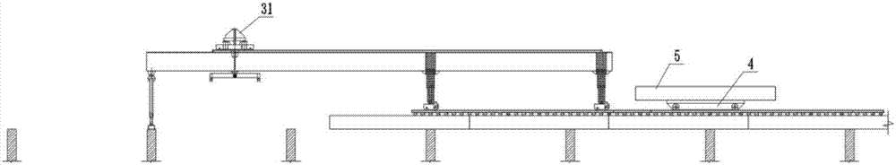
[0047] see figure 1 and figure 2 As shown, the present invention provides a wide-body steel girder erecting machine, which includes a main structure 1 , a supporting mechanism 2 , a lifting device 3 and a running device 6 .

[0048] The wide-body steel girder erecting machine in the present invention adopts a double girder structure, that is, the main structure 1 includes two oppositely arranged girders 11, and the two ends of the two girders 11 are fixed with a main girder 12.

[0049] The supporting mechanism 2 includes a front leg 21 , a middle leg 22 and a rear leg 23 fixed on two main beams 11 . Wherein the front outrigger 21 stands on the existing bridge beam 7 and is mainly used for supporting. The middle outrigger 22 and the back outrigger 23 are mainly used for walking on the bridge deck. In addition, the front leg 21, the middle leg 22 and the ...


PUM


Abstract

The invention discloses a wide-body steel girder erecting machine and a girder erecting method thereof, and relates to the technical field of bridge engineering construction, comprising: a main structure, which includes two oppositely arranged main girders, and the two ends of the two main girders are fixed There is a main beam connecting two main beams; a supporting mechanism, which includes front outriggers, middle outriggers and rear outriggers fixed on the two main beams, and the front outriggers, middle outriggers and rear outriggers are all set There are telescopic devices, which can extend and contract the front outriggers, middle outriggers and rear outriggers; and hoisting devices, which include a crane and a spreader. The spreader is set under the crane, and the crane can be retracted and retracted. The spreader is lowered, and the crane can also move longitudinally and laterally along the bridge. The present invention can realize the efficient, stable and safe erection of wide-body steel girders under the working conditions of existing bridge support space, limited foundation bearing capacity and inability to use large-scale equipment.

Description

technical field [0001] The invention relates to the technical field of bridge engineering construction, in particular to a wide-body steel girder erecting machine and a beam erecting method thereof. Background technique [0002] The first batch of large road-rail bridges in China have gradually entered the maintenance cycle with the continuous growth of service life and the increase of traffic flow. The bridge decks of existing bridges and highways are generally of concrete structure. Long-term use will cause local concrete blocks to be damaged and fall off, causing serious safety hazards to the operation of railway business lines. The replacement of bridge decks has become one of the important contents of this type of bridge maintenance. [0003] New bridge decks usually use long-lived orthotropic steel girder decks (hereinafter referred to as steel girders). Due to the limitations of existing bridge structures and the requirements for installation efficiency, the new steel...

Claims


Application Information

Patent Timeline
Patent Type & Authority Applications(China)
IPC IPC(8): E01D21/00
CPCE01D21/00
Inventor 娄松娄廷志王亚龙张武江湧王戒躁张超福杨先权蔡巍刘曙光贺海飞陈勇金博宋东东舒昕向阳
Owner WUHAN BRIDGE SPECIAL TECH CO LTD CHINA RAILWAY MAJOR BRIDGE ENG BUREAU
Why Eureka
Try Eureka